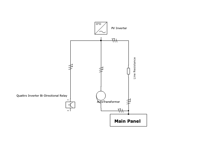
Let us say we have ac coupled PV grid-tie setup with Quattro/Multiplus (i.e. grid backup) - to keep it simple, only AC out1 in Quattro outputs is in use. In such setup, the PV output is also routed to AC Out 1 port of Quattro/Multiplus. Now, if we add Victron autotransformer for load balancing, its input will be connected to same AC Out 1 port of Quattro. Autotransformer output is connected to main panel. That is, Quattro output will be balanced through it.
I can think of Quattro as a bi-directional relay in series with PV output - charging as needed, and producing excess power to assist the PV when the grid is out. So, when the autotransformer (aka AT) is also connected, it seems to me that it now forms a parallel circuit to PV connection to Main Panel. So, any PV output that is going to main panel will now be routed through both existing PV lines and via autotransformer lines (with current split inversely proportional to resistance of each line). The same should be the case when Quattro is producing power - it will use both PV and AT connections to main panel.
I am including a single line diagram below outlining the above. Please note that in the diagram Quattro acts like either a sink or source (bi-directional relay).
The question is if my understanding above is correct. If it is correct, then it seems to me that autotransformer will indeed be in use all the time the power is produced by either PV or Quattro, not only when Quattro is inverting during off-grid. In case I have got anything wrong here, please correct me.

