question

rockatron avatar image
rockatron asked

Is everyone aware that a BP100 can catch fire if you allow current to flow through it in both directions?


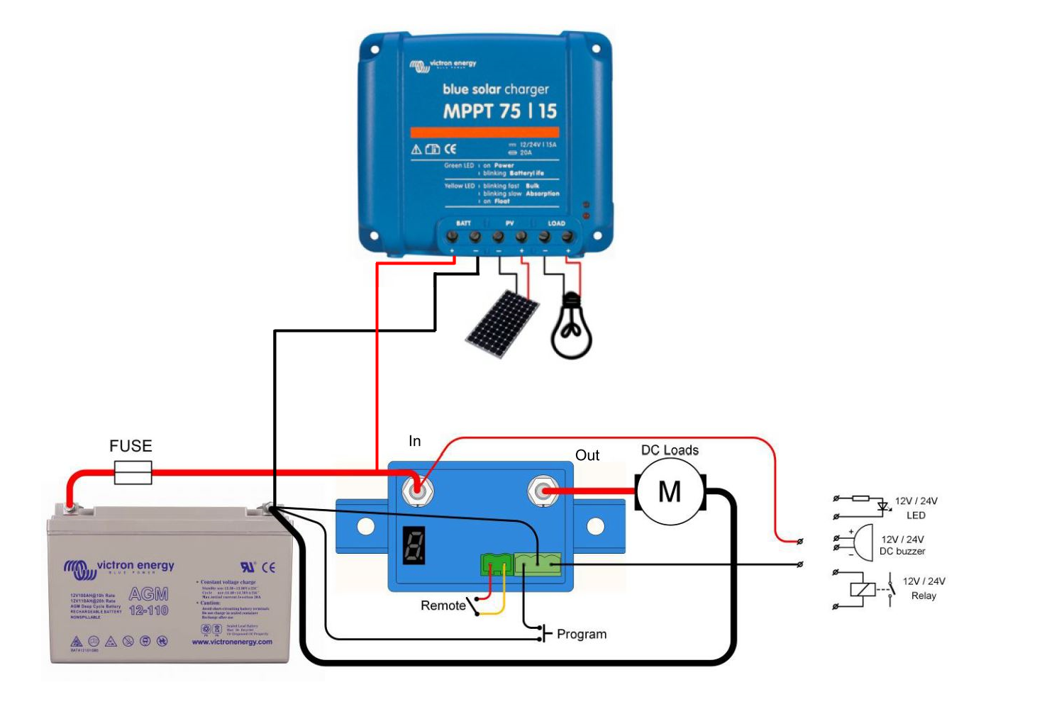
I am merely reposting a seemingly important issue discussed here: https://community.victronenergy.com/questions/2030/vebus-bms-with-2-battery-protect-alternative-layou.html

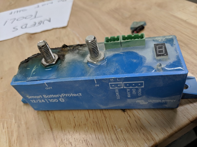
A BP100 caught fire with a 60AMP charging load to the battery and we are now told that all Battery Protect modules are only designed to allow current flowing from the battery to devices, no charging current is allowed to pass through a BP module into the battery.

Is this common knowledge or are you surprised as well?


EDIT ** I now see the caution listed by Victron at the very end of the manual beyond the setup diagram, not in the actual "Engligh" or any other foreign language instructions. Also the website now clearly states this issue on the listing page, which I do not remember seeing when I purchased mine 8 months ago. Thanks for the feedback**


This applies to all Battery Protect Modules and was confirmed by Victron staff in the following thread.

https://community.victronenergy.com/questions/5217/tesla-model-s-battery-multiplus-can-not-turn-on-in.html


Battery Protect
5 comments
2 |3000

Up to 8 attachments (including images) can be used with a maximum of 190.8 MiB each and 286.6 MiB total.

atomix avatar image atomix commented ·

Shocking. I had absolutely no idea about this. I was just about to buy a BP65 and would have wired the MTTP charge going through it. I can't see any reference to this critical limitation in the manual or datasheet and considering it could result in a fire (!), i'm more than a little disappointed with Victron for not making this absolutely clear.

0 Likes 0 ·
wkirby avatar image wkirby ♦♦ atomix commented ·

It is clear on the product web page.
It is also mentioned in the Datasheet but perhaps it needs to be clearer there and the manual should be updated.

0 Likes 0 ·
rockatron avatar image rockatron wkirby ♦♦ commented ·

Thanks for the info, I now see the fine print at the end of the manual as opposed to being in the actual instructions. As to the website listing, I feel this has only been updated in the last 8 months since I purchased my unit but can not say for sure. I am glad it is at least documented but should definitely be more clear in the manual. Thanks.

0 Likes 0 ·
Tom avatar image Tom rockatron commented ·

Yes I researched it also and my ignorance did not understand the fine print. I am now correcting and making modification to my set up. I also purchase both my BPs a year ago and did not see the fine print.

I would think Mosfet switches manufactured in the BP should work in both directions, but I am not an electrical engineer to fully understand.

I would like to get your email if you can PM me?

Tom

0 Likes 0 ·
Tom avatar image Tom atomix commented ·

I suggest you review the Victron VW Van project. The BP65 can still be used between the MPPT and battery as a over voltage remote switch but it has to be connected with the BP65 battery lug connected to the MPPT and the load to the battery. This allows the charging from the MPPT to flow in the correct direction. Again the schematics in the Victron VW Van project shows this.

If I am incorrect someone please comment.

0 Likes 0 ·
3 Answers
eliott avatar image
eliott answered ·

Hi! I think it is never enough to emphasize this, as it might go unnoticed for a few people.

it is stated though on the website product page:

The BatteryProtect is not designed for reverse currents from charging sources

and the documentation:

Caution: uncontrolled reverse current will flow through a Battery Protect if Vout > Vin. Therefore never use a Battery Protect for battery to battery charging.

2 comments
2 |3000

Up to 8 attachments (including images) can be used with a maximum of 190.8 MiB each and 286.6 MiB total.

rockatron avatar image rockatron commented ·

Thanks for the info, I now see the fine print at the end of the manual as opposed to being in the actual instructions. As to the website listing, I feel this has only been updated in the last 8 months since I purchased my unit but can not say for sure. I am glad it is at least documented but should definitely be more clear in the manual. Thanks.

0 Likes 0 ·
ben avatar image ben ♦ rockatron commented ·

Yes, it was updated more recently than 8 months ago, and it should still be made clearer, in my opinion.

0 Likes 0 ·
Justin Cook avatar image
Justin Cook answered ·

Victron definitely states that you shouldn't wire this device in a manner which allows reverse current through it, but we've spoken to them about emphasizing this more, and we've updated our own product listings with very pointed language stating that these are unidirectional devices only and cannot be used as bi-stable switches. The most common failure I see is simply that the FETs fry closed (or occasionally open) when current is run backward through them, and overheating is definitely occasionally evident particularly in the plastic-cased units, but usually it's limited to case malformation rather than actual fire.

One downside(?) of purchasing professional-grade electronics is that the manufacturer usually assumes that their products are being installed by professionals who have read and fully understood the instructions and the limitations of the products being installed; that being said, given the widespread misunderstanding of this device's operation and limitations, I think Victron will likely soon update the wording of their warnings.

2 |3000

Up to 8 attachments (including images) can be used with a maximum of 190.8 MiB each and 286.6 MiB total.

Matthias Lange - DE avatar image
Matthias Lange - DE answered ·

All BPs are clearly labeled with IN and OUT.

So I don't understand how someone could think it is a good idea to connect a charger at OUT and let the current flow in reverse through the BP.

The schematic in the manual show's how to connect a charger to a BP (charger output at BP IN and BP OUT to the battery.

10 comments
2 |3000

Up to 8 attachments (including images) can be used with a maximum of 190.8 MiB each and 286.6 MiB total.

atomix avatar image atomix commented ·

My 100/20 MTTP Solar Charge Controller has a load out which can source power from the battery whether there is PV coming in or not. So wiring my charge controller to the BP IN could still result in reverse current flow (not that I can see a reason to put the BP in between MTTP and Bat.).


As this is a safety issue I would recommend putting a warning that current may only be allowed to flow in one direction very clearly, not only in the manual, but actually on the device.

0 Likes 0 ·
kai avatar image kai ♦ atomix commented ·

I can kind of see this from both sides. Its not immediately intuitive that the device is not bidirectional (for the typical end-user, and without going into the datasheet). So from that perspective a label is an answer.

On the other hand, professionals (as in paid engineers, installers etc) would more than likely to fully read and understand the documentation because its their job, and know that assuming devices are bidirectional without checking is not a good idea in general. Safety issues can arise from any number of configuration errors and there isn't enough space on the units for all those stickers.

Victron knows that their equipment is sold to both groups (professionals and end-users), so it'll be interesting to see how they respond.

0 Likes 0 ·
atomix avatar image atomix kai ♦ commented ·

Yes I can see that professionals would be expected to have a full understanding of the device and it's limitations. I'm not a professional electrician and much to my embarrassment I completely missed this limitation.

In the design industry however, we don't leave things to chance when safety is concerned and there are methods for gauging the need for/what type of safety should be implemented. A Mode Failure Effect Analysis looks at what are the effects of a danger, not just the likelihood of it occurring. If the failure can result in a fatality then additional steps are usually taken to enhance safety. That could simply be a clear warning label, or a full blown active protection and redundancy system.

That is why, for example, we always include a warning for electric shock in high voltage systems. Even though the only people who would normally be exposed to this danger are professionals and should already be aware of the danger. The effect of the risk is just too severe.


P.S I'm not recommending a label like above. I'm just making the case that maybe some sort of explicit label should be included in the instructions and on the device, even if most installers are expected to already be aware of the issue.

0 Likes 0 ·
Matthias Lange - DE avatar image Matthias Lange - DE ♦ atomix commented ·

???

Why could there be a reverse current through the BP if you connect the MPPT at BP IN?

0 Likes 0 ·
David avatar image David Matthias Lange - DE ♦ commented ·

As Atomix said, if you use the Load Terminals.

If you have an MPPT with Load Terminals in use, then when the PV is providing a positive charge, the power is flowing from MPPT to Battery. But when it is dark, the power is flowing from Battery to MPPT i.e. in the opposite/reverse direction.

0 Likes 0 ·
Matthias Lange - DE avatar image Matthias Lange - DE ♦ David commented ·

If it is connected as I think:

There can't be a reverse current through the BP because the MPPT is connected directly to the battery.

Low battery disconnect for loads at MPPT load can be set via the VictronConnect app.

0 Likes 0 ·
Mark avatar image Mark ♦♦ Matthias Lange - DE ♦ commented ·

The BP can be used as a DEDICATED low voltage load disconnect OR a DEDICATED high voltage charger disconnect, as long as its wired in the correct orientation (power SOURCE connected to the 'battery' side).

In the VW Van install they use one BP connected to the loads as a low voltage disconnect and a second BP connected to the MPPT output as a high voltage charger disconnect;

https://community.victronenergy.com/storage/attachments/2521-van-solar-full.png

There is no notable reverse current flow from the battery into the MPPT at night when the MPPT is off (if you check it with a BMV and everything else off you will see that it indicates ~0.00A).

Obviously all circuits still need to be properly protected with fuses/circuit breakers to cover a short circuit or over-current fault.

0 Likes 0 ·
Tom avatar image Tom commented ·

Not sure where your BP lugs say in and out. My BP230 is labeled Batt and Load.

Also it is confusing when Victron sells Chargers, Inverter Chargers, and Inverters and you would think you can use a BP with all Victron equipment. Also it is confusing when using a BP as it has both low voltage shut off and over voltage shut off programed in the unit so if it has OVSO you would make the assumption it would work with chargers. Why else would the BP have an OVSO, but to protect the battery from over charge?

0 Likes 0 ·
Matthias Lange - DE avatar image Matthias Lange - DE ♦ Tom commented ·

Your BP maybe is an older one now days they are labeled with IN and OUT.

If you use Victron inverter, charger and/or inverter/charger you don't need a BP because you can program all devices.

The over voltage cut off will protect the load from over voltage.

If you want to use a BP with a charger you have to connect the charger to IN and the battery to OUT (as shown in the last schematic in the manual)

0 Likes 0 ·
Tom avatar image Tom Matthias Lange - DE ♦ commented ·

Thank you as yes I am aware of that now. I am moving my BP220 out of the charge loop. The BP220 seems to label the lugs differently. It is not that old and the Data sheet shows the BP220 labeled with Batt and Load.

0 Likes 0 ·