I am trying to replace my cheap chinese 200VA inverter by a new setup using a Multiplus 24/800 (that one with the cheap plastic case like the small Phoenix inverters) and a Cerbo-S. The existing 100VA/2x12V LiFePo (integrated BMS w/o external interface), balancer, smart shunt, MPPT 75/15 + 400Wp PV panel I kept from that system.
The old inverter had a simple transfer switch, switching to AC-out to AC-in if the battery voltage was below a certain threshold and back if a threshold was high enough. This setup was supplying a home server. It did also harvest PV power whenever possible. There was a kind of USV behavior in case of ACin loss (with a third inverter shut-off limit for the battery) and the inverter passed this info via MQTT on to the server, so I could quickly shut it down before the battery was depleted. Charging was done by the MPPT only (with LiFePo setup).
Ok, this was a simple, transparent, straight-forward setup, where the only limitation is, that it could handle 200VA max, which became a problem after I replaced my new server with a higher peak power requirement. Thus, I thought to give the 800VA Multiplus a try. First I noticed, I can't really set up such a simple system anymore with the multiplus. So I went to an ESS setup and also hoped for some improvements in respect to batterly handling/optimisation to justify all this costs/overhead...
I set up everything according to the ESS trainings I found. Of course, all components are updated to the latest firmware versions prior to the setup. So far so good. One issue I noticed is, that all of them assume the existance of a BMS for LiFePo which I don't have (and my old inverter didn't require as well). So I selected in the ESS assistant the third setting "LiFePo / other BMS". I kept the default LiFePo settings for the battery type set in the charger tab - which were anyhow the same as for my previous MPPT charger (VE.Bus BMS checkbox is not set as well). There is anyhow not so much to set up in the assistant itself and the Cerbo ESS settings (which are visible, so ESS is enabled)...
I am aware that I also need to add a redundant anti-islanding protection for this device and what this is (I am a trained engineer in the industrial power field). Anyhow, for now I am testing on the output of my old USV/inverter connected to my old server (so no direct grid connection and a constant load always available, in case the multiplus feeds back power to the line). Adding protection and registering at my grid supplier up to 800VA later on is also no issue.
I monitored the settings in VRM, no display on Cerbo connected. In principle it is working, it keeps AC-In at 0W and takes the energy from the battery (which was fully charged, shunt also synchronised to 100% SOC). Over night with 11W self-consumption of Multi, Smartshunt and Cerbo the SOC according to the shunt went down to 93% or so (100Ah/2x12.8V battery). This was OK.
Now my problems started:
.) I see that the multiplus issued low-bat warnings all night long (red LED is also blinking), again: there was no load and the battery is still practically fully loaded. I have no DC connection issue, wiring is 16mm² as recommended (before the fuse to battery it is even 25mm²). The detailed graphs in VRM also shows that the battery was always at 26.57V...26.55V. Even when connecting a 25W load, the voltage was stable and not dropping. I don't want to test larger loads for now, as I see that the ESS regulation on ACin is extremely slow - also the 25W when switched off "shoot back" in the grid for 10s of seconds or so until it stabilises to 0W again - according to the Cerbo monitor. To the grid of course this is no issue and it will anyhow not happen often, as the load will be "quite stable", but I don't want to damage my USV for this test setup. Unfortunately, the warning logged in Cerbo is quite useless, as it does not include the value it was created upon (it it is 0V, so some input is missing or some voltage which is below some set threshold).
.) The MPPT should be configured, as it shows either "off" (over night) or "ext. control" when there was sun in the morning. But even if there is the internal 25W load, it continues discharging the battery and not enabling the MPPT. I tried with the 400Wp PV as well as with a small 50Wp panel, which in principle couldn't feed more than ~15W or so at that time of the day. Just to be sure it is not because I set the 0W target to ACin and the large panel would exceed that actually power on the load and this switched off.
.) After disconnecting ACin, I noticed that the MPPT was starting (after a few minutes) to deliver power to the DC side. As assumed, with the small PV - it only provided part of the required power, a small remaining part came from battery. With the large PV, power flow went into battery and inverter/load. As expected, that should be ok. But then I connected the ACin again and the MPPT immediately stopped, so load was supplied only from the battery again! Wtf...
What I am really missing is a basic state diagram of this ESS assistant, showing the general control behavior and its relevant input parameters controlling it. This way it is reading a lot of manuals and watching tutorials and ending up in trial and error experiments...
I am currently assuming that my problem is the missing BMS connection for the LiFePo configuration. This could fit somehow to what I see. But I am never sure, as I notice that the ESS reacts quite slow on certain changes.
So my next try would be to use any other battery setting (and not LiFePo), but it is not clear for me what the impact could be. But maybe I missed something else for such setups w/o BMS (or better: with BMS based on voltage thresholds instead of an interface connection).
I don't want to damage the Multiplus, as I might need to send it back to the shop where I bought it, if I can't solve the problem. And I obviously don't want to destroy my batteries in that process. Then I'll get just a cheaper 24V/500VA inverter and do the AC switching with a relais and small uC (which I meanwhile think would be the easier and more reliable solution for that problem...).
So maybe someone else uses a similar configuration out there with LiFePo batteries w/o BMS connection and as an idea what can be done here. I am aware I could get some 24V batteries with CAN connection, but the batteries I have are totally fine and I don't want to replace them just because of some software issue...
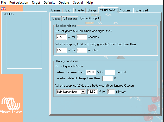
I attached here some screenshots from Cerbo, the relevant VRM battery/warning logs and the config:
Thanks in advance :-D