Hi
This is a follow-up to https://community.victronenergy.com/questions/251430/quattro-ess-not-fully-charging-from-grid.htmlbut detailing what I've done and discovered since - hope it helps someone.
My system consists of:
- Quattro 48/10000/140
- 2 x SmartSolar 250/60 with 6.4kW PV
- 1 x SMA SB4000TL with 4kW PV on AC1 out
- Smartshunt between Quattro/MPPT and the batteries
- 2 x Batteries (DIY 16 x EVE LF280K with Seplos 48V 200A BMS (10C))
- Cerbo GX
- 1 x ET112 Grid meter on USB
- 1 x ET112 on AC PV on USB
For over 12 months I've been running with the Smartshunt configured as Battery Monitor in Settings->System Setup, DVCC turned off, and the Seplos BMS connected via CAN.
All seemed well except:
- No visibility of any cell voltages on the Cerbo (see below)
- Incomplete charging from Grid (caused by the Cerbo responding to the Seplos BMS even though it is not configured to do so)
So I started digging and changing things to see if I could improve things.
I was running version 2.9 of the Seplos firmware, but after seeing (Off Grid Garage) Andy's excellent spreadsheet https://docs.google.com/spreadsheets/d/1E7zX6uXqczvpEEJKD8jER31LWkNqWMgvUytVCVfMvlg/edit?usp=sharing comparing the different firmware versions, I decided to try version 2.8.
Amazing! What a difference! All of a sudden I get details from the Seplos BMS coming through to the Cerbo.
So I decided to enable DVCC so that the BMS is in proper control of charging and it works!
I'v feeling really good at this point, but then I noticed some things that did not make sense.
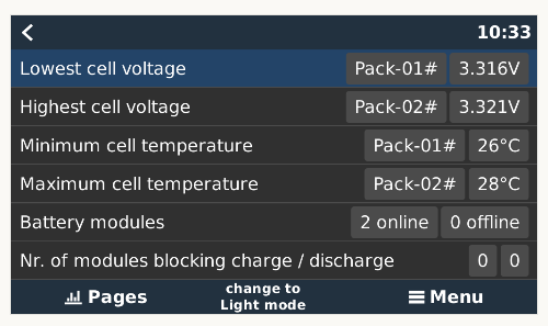
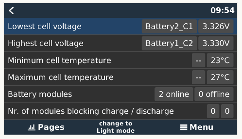
I can see which is the highest cell voltage and which pack they are in, but not the Cell ID.
Is this just a display problem? So I take a look at the info on DBus and MQTT. Nope, it is the same.
I then took a look at the Seplos firmware. After a little bit of (ahem) reverse engineering, I identified the function that was compiling the "Pack-0x #" messages and that is all that is being sent. The CAN frame only has room for 9 bytes and it is not even trying to send the cell id.
I raised this as a bug with Seplos but they are very unlikely to fix the problem suggesting that I either use newer firmware (which is broken) or their PC application - not helpful.
A little frustrated, but not defeated, my attention turned to the RS485 connection on the BMS. There's quite a bit of info out there on the protocol and even some code!
So, could I connect each BMS to the Cerbo and get all the info I desired, and proper control of charging. It seemed possible so I decided to give it a try.
Huge shout out to Louis and Manuel of https://github.com/Louisvdw/dbus-serialbattery - covers a large number of serially connected BMS including Seplos.
But that is only part of the answer. The Victron system can't aggregate the info from multiple BMS by itself. For that you need another bit of software to create a single virtual battery. I decided to go with https://github.com/Dr-Gigavolt/dbus-aggregate-batteries which is one of a few choices detailed on the DBUS-SerialBattery instructions.
Back to the hardware side - of course there were some problems to solve!
First up is how to connect two BMS via 485 to the Cerbo?
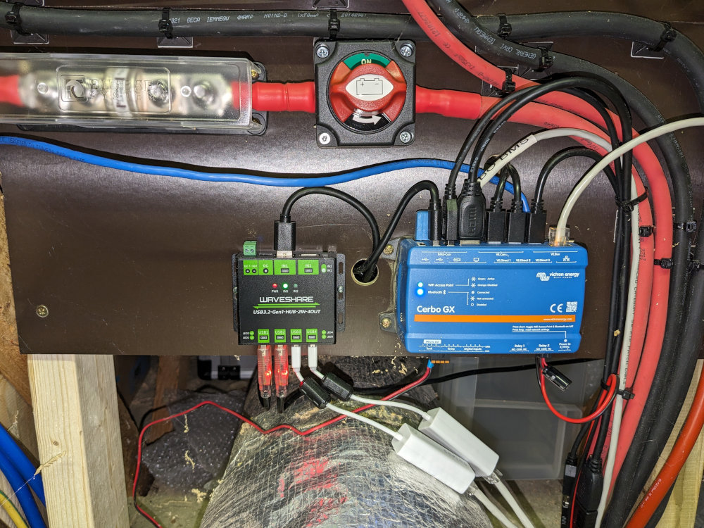
I had some genuine FTDI RS485 USB cables in the cupboard so hooked them up to the two BMS.
However, there are only 2 usable USB ports on the Cerbo and they were being used for the two ET112 energy meters.
No problem I thought! I'll just throw in a USB hub I had lying around on one of the Cerbo ports and connect one ET112 and the two BMS to that. Perfect!
Nope!
Although it seemed to be working at first, every now and again the ET112 grid meter would disappear and as a result the system would stop charging and switch to passthrough. Not good.
The only resolution was to unplug/plug the USB device or reboot.
This was tricky to track down!
It turns out that there are some problems in the Linux kernel with regard to multiple USB serial adapters. There are some suggestions that this is resolved on newer kernels but the VenusOS kernel is quite recent and really should not have the problem. There are also suggestions that fake FTDI chips are to blame, but the ones I'm using are genuine. However they are quite old and there were some suggestions that newer adaptors work better.
As it happens, when I bought the Seplos BMS, I bought two of their 485 adaptors. Plugging them in I found they are FTDI based and appear to be the newer type. So I switched to the "white" Seplos adapters, and it did not make any difference!
Frustrated again...
But not defeated!
There were also suggestions that having multiple serial adaptors on a hub could be a problem.
So I dug out another hub, connected both ET112 to one hub, and both BMS to the other hub.
Big difference!
Now the two ET112 are completely stable.
It turns out that when the ET112 were on the same hub as the BMS, occasionally one of the BMS adaptors would go wrong, throw a kernel error, but also cause the ET112 to disconnect. Now that the ET112 were on their own hub they were much happier.
But, and there is always a but, the two BMS on the other hub were still not 100% stable.
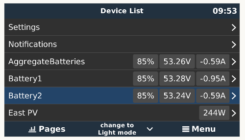
At this point the two BMS are connected via the Seplos 485 adaptors into their own hub and then into the Cerbo, using dbus-serialbattery to communicate to each BMS, and dbus-aggregatebatteries to create a single virtual BMS which is configured as battery monitor in System setup and DVCC.
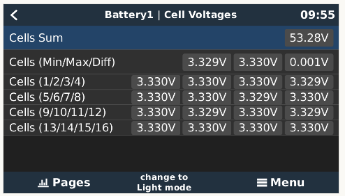
All is working including individual cell voltages, min/max/diff, temperatures, everything. Charging is working exactly as I expect with the BMS in charge of all thresholds (whether that is a good thing is a separate topic!)
However, as I just said, the connection to the BMS is not 100% stable.
When one of the BMS disappears, dbus-aggregatebatteries fails and tries to restart but the BMS won't come back without a reboot or replug.
Not good.
Looking at /data/log/messages I see errors like
user.err kernel: [18796.494858] ftdi_sio ttyUSB3: usb_serial_generic_read_bulk_callback - urb stopped: -32
user.err kernel: [18796.503035] ftdi_sio ttyUSB3: failed to set flow control: -32
and similar.
So why is there still a problem?
Well, it seems there are two kinds of hub!
Before anyone suggests I need to use externally powered hubs, let me just say I tried that and it makes no difference. These serial adaptors take so little power that self powered hubs are more than sufficient.
No, what I'm talking about is STT vs MTT.
Single Transaction Translator vs Multiple Transaction Translator.
Most hubs are STT. Very few are MTT but there are a few out there.
The MTT hubs have one TT per output port versus a single shared TT.
It seems that to improve the situation with these serial adaptors (which really might be down to a kernel problem) using an MTT hub is the way to go.
I first ordered a pair of Waveshare USB-HUB-2IN-4OUT hubs from PiHut because their description said MTT. However, on receipt I tested them and found they are only STT. PiHut agreed I could return them and they said they would correct their description.
I've now ordered the Waveshare USB3.2-Gen1-HUB-2IN-4OUT from Amazon which should be with me in the next day or so.
I'll report back once I've had a chance to test them.
Phew!
John