question

Alex Pescaru avatar image
Alex Pescaru asked

Error code #29 - Over-charge protection on constant conditions

Hi All,
As per title and pictures below...
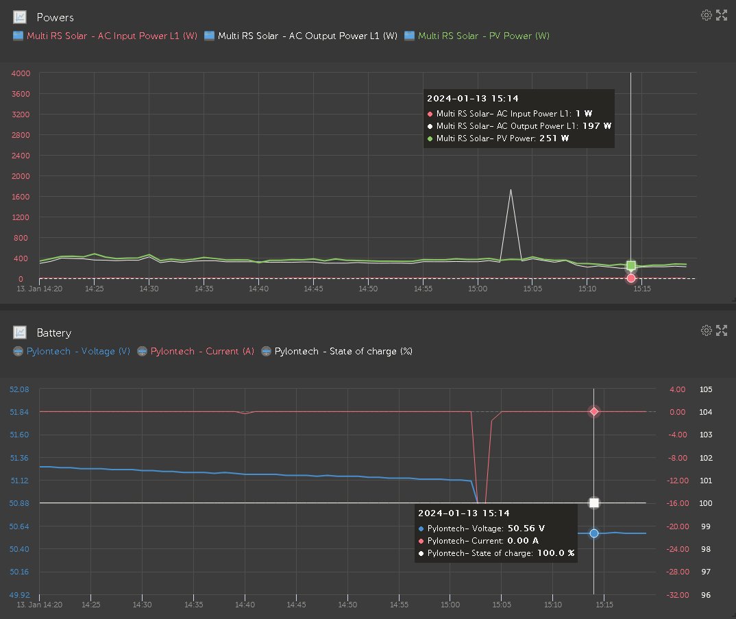
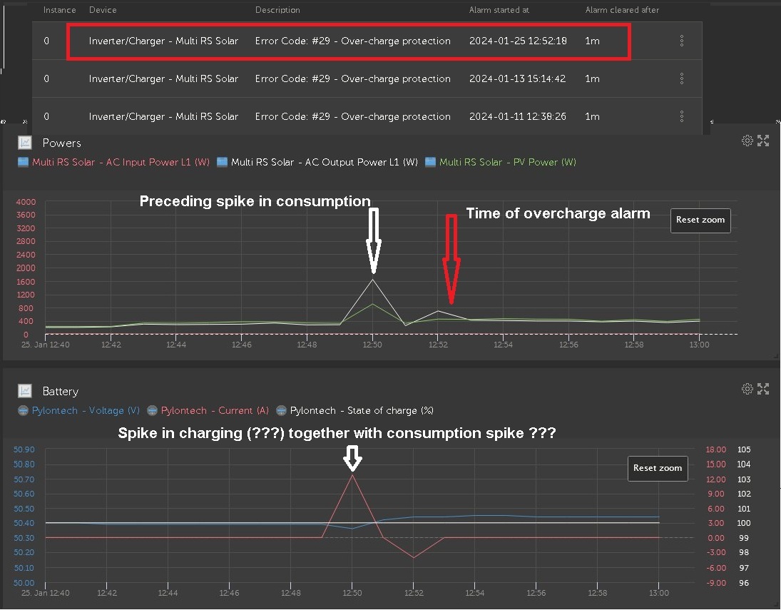
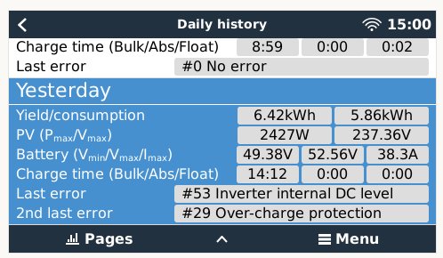
Happened twice already, solved itself after 1 minute.
An almost constant consumption, without rapid change conditions.
Multi RS Solar connected through Cerbo to Pylontech battery.
Battery on idle as reported by BMS and leds, SOC 100%.
All power consumption, about 200W, supplied by solar.
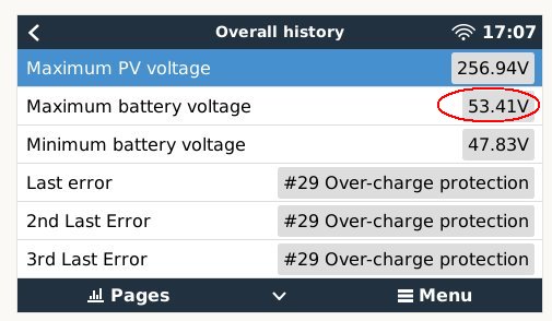
Strange as no causes from the inverter documentation applies:
- no oversized PV array config (5 panels x 50VOC on each tracker)
- battery settings dictated by the master Pylon BMS (6 x US2000C battery bank)
- no another charger in the system
Any advice is welcome.
Thank you in advance!

Markers below at exact time of last occurrence...

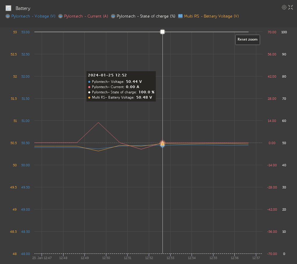
Batteries were idling, with the VRM status switching between ESS#3 and ESS#4.

alarm.jpg

status.jpg

bug reportMulti RS
alarm.jpg (17.0 KiB)
status.jpg (93.6 KiB)
8 comments
2 |3000

Up to 8 attachments (including images) can be used with a maximum of 190.8 MiB each and 286.6 MiB total.

Alexandra avatar image Alexandra ♦ commented ·

@Alex Pescaru

Defined not over panelled.

Not more than 8x float voltage on voc in min temps.

Or as in you haven't loaded the trackers up?

Weird how the pylon is at 100% but 50v since float is 51v bulk 52v what is the battery bank exactly? (Model and number of modules connected)

0 Likes 0 ·
Alex Pescaru avatar image Alex Pescaru Alexandra ♦ commented ·

Hi @Alexandra

Thanks for responding,

Not over panelled means each tracker has 5 modules with 50V VOC. That is 250V, way below 50x8 = 400V rule.

Pylons are 6 x US2000C.

Yes, the Pylons are idle and during idle period, remember, we've talked about that on the link below, where I've mentioned that sawtooth behavior. In the moment the error appeared, the Pylon voltage was on the down-slope, idling.

https://community.victronenergy.com/questions/247981/battery-consumption-when-no-need-to.html


0 Likes 0 ·
safiery avatar image safiery commented ·
I have multiple customer sites with same issue at present. We will escalate this as we cant find the root cause.
0 Likes 0 ·
Alex Pescaru avatar image Alex Pescaru safiery commented ·

Hi @safiery

Did you managed to solve this issue?

Since your reply on Jan 22, on my system the error has appeared 3 more times...

Alex

0 Likes 0 ·
the-doon avatar image the-doon commented ·

May I ask which pair of Can sockets you are plugging the patch lead from the batteries into on the Cerbo?

0 Likes 0 ·
Alex Pescaru avatar image Alex Pescaru the-doon commented ·

Hi @The Doon

The only one available for this. There are only two CAN sockets on Multi RS.

One to the Cerbo and one for the CAN terminator.


0 Likes 0 ·
the-doon avatar image the-doon Alex Pescaru commented ·
Which set on the Cerbo. VE.Can or BMS-Can? I’m specifically asking about where the patch lead from the batteries plugs into on the Cerbo.
0 Likes 0 ·
Alex Pescaru avatar image Alex Pescaru the-doon commented ·
Sorry, I was not paying attention...

On the Cerbo, the batteries are connected to the BMS CAN port.


0 Likes 0 ·
6 Answers
Alexandra avatar image
Alexandra answered ·
Ah right.

I see your bank has Increased since that post. Nice.

The #3 & 4 are battery related states. Possibly the error #29 is triggered by battery behaviour.

What I do see with pylontec they go idle they sometimes switch to allow power state. maybe that is what is happening then they switch to a low power state/protect mode? I am guessing here. I have not experienced it myself but had a conversation once with someone who had an issue with them not being fast enough to wake up from that state.


1 comment
2 |3000

Up to 8 attachments (including images) can be used with a maximum of 190.8 MiB each and 286.6 MiB total.

Alex Pescaru avatar image Alex Pescaru commented ·

Yep, I wanted the bank to be able to supply for at least two days.


Even on idle state the batteries don't switch off the terminals. They remain connected all the time and they are able to instantly provide power, even when idle.

Problem is that the voltage, especially on its upward evolution, is controlled by the inverter and not the batteries.

Any battery will only go down voltage-wise if they are left alone. So only the inverter could overshot. And this could be because, maybe, of some improper close loop regulation with a too big hysteresis.

And when adding batteries, this could only help in the good direction. The more the batteries, the bigger the "opposing force" to sudden change in voltage. They are one big capacitor....

I will monitor more closely and see what's happening.

Maybe the developers could shed a little light on this about how the #29 is handled and which conditions are taken into account.

Please @Guy Stewart (Victron Community Manager) , if you could help with this, any advice is much appreciated.

I know from the changelog that on version 1.12 (May 25, 2023) it was introduced a "Fix false-positive over-charge protection (error #29)", but maybe it's still too sensitive ??

And in the manual it says "This error will auto-reset once the battery voltage drops below the float voltage".

From where the inverter is taken the float voltage value, over which it triggers the #29 error?

Because the BMS is only supplying a single voltage, that 53.2V good for everything: bulk, absorption, float (???).

But on Battery section of VictronConnect you can define all voltages individually.

So, the firmware which one is considering to be the triggering one? VictronConnect one or BMS one?

Thank you a lot for your efforts!

Alex

0 Likes 0 ·
Alexandra avatar image
Alexandra answered ·
Is the inverter reading the battery voltage correctly?
1 comment
2 |3000

Up to 8 attachments (including images) can be used with a maximum of 190.8 MiB each and 286.6 MiB total.

Alex Pescaru avatar image Alex Pescaru commented ·

Yes.

Depending on the current, the inverter is following the BMS voltage pretty accurately.

For example, now, for a consumption current of 7.5A, BMS says 49.76V, the inverter says 49.74V, so only 20mV difference, probably because of the cable drop.

At about 60A, during charging, the difference is about 300mV, so only 0.6% drop. Pretty good I say...

0 Likes 0 ·
vward avatar image
vward answered ·

Just a guess, before we had set the correct tail current set in our Smart Shunt, we had that issue. Maybe check that for your BMS? The default tail current of 4% was WAY too high for the size of our battery bank, which is sized to give us 4 days of autonomy.

1 comment
2 |3000

Up to 8 attachments (including images) can be used with a maximum of 190.8 MiB each and 286.6 MiB total.

Alex Pescaru avatar image Alex Pescaru commented ·

Thank you for your answer.

When the Cerbo detects the Pylontech BMS, a lot of settings in the Battery section are overridden and all is handled through Cerbo - Battery BMS dialog and then sent to the inverter for its processing.

In my case, the tail current is set to Disabled.

0 Likes 0 ·
Alex Pescaru avatar image
Alex Pescaru answered ·

Hi developers,

@Guy Stewart (Victron Community Manager) , @Thiemo van Engelen (Victron Energy staff) , @mvader (Victron Energy)

Additional info on this error, which still seems to "plague" the Multi RS Solar, like @safiery also mentioned 3 days ago...

It seems that during a short spike in consumption, the battery current also spiked in the positive way, charging-wise, like the inverter tried somehow to compensate the current draw that the battery "supposedly" should have contributed to the load.

Of course, after a couple of minutes, the error #29 - Over-charge protection appeared....

See below.

Thank you!

consum.jpg


consum.jpg (193.0 KiB)
6 comments
2 |3000

Up to 8 attachments (including images) can be used with a maximum of 190.8 MiB each and 286.6 MiB total.

thanar avatar image thanar commented ·
Could you also add the DC BUS voltage, as reported by the charge controller, to the graph?
0 Likes 0 ·
Alex Pescaru avatar image Alex Pescaru thanar commented ·

Hi @thanar

If you are referring to the internal DC Bus voltage of my Multi RS, the one about 400 volts, I don't have the possibility to log it.

If you are referring to the battery voltage, as reported by the Multi RS, here it is below, following very closely the battery voltage reported by battery BMS, only with about 40mV more.

Thanks,

Alex

voltages.jpg

0 Likes 0 ·
voltages.jpg (63.7 KiB)
thanar avatar image thanar Alex Pescaru commented ·

Indeed; Voltage as reported my the MultiRS is almost the same. Could you please measure the battery voltage at the battery terminals, when battery is full and near the time when it pops the alarm?

It could be that the Pylontech's BMS is cutting off charging, and the DC BUS voltage shoots up momentarily. We would be able to see this if you had an extra charge controller that would log its own values, with no connection to the battery ofr the GX system.

0 Likes 0 ·
Alex Pescaru avatar image Alex Pescaru thanar commented ·


In all the cases the battery was on Idle for quite some time, with 100% SOC and with the CCL on 0 (zero) Amps.

Voltage at battery terminals, measured with a professional meter, are just a few mV different that Multi RS ADCs, which is commendable for Victron.

Also the Cerbo reporting the ESS#3 state.

No other charge controllers are in the system. Just the Multi RS, Pylontechs and Cerbo.

In all cases, around/before the moment when it happens, it was a big load for several seconds, usually a microwave oven.

The load was always supplied successfully by the energy from solar, without the need of the battery adding to the energy necessary.

Of course, during those moments, like I've pointed out, there was a spike in the battery current, but towards the battery, not from the battery, which is odd...


Looking at the Multi RS overall history, for sure at some point there was one or more overshoots in voltage regulation as seen on the picture below.

Considering that the inverter limits the charge voltage for Pylontechs at 52.4V, that 53.4V is quite high.

1.jpg

0 Likes 0 ·
1.jpg (32.2 KiB)
thanar avatar image thanar Alex Pescaru commented ·
Looks like the BMS is cutting out. I would try lowering the charge voltage just by 0.2V through the DVCC settings.
0 Likes 0 ·
Alex Pescaru avatar image Alex Pescaru thanar commented ·
What do you mean by "BMS is cutting out" ?

Because if I look at the BMS connection to Cerbo, there is no disconnection, no error, the packets always reach Cerbo from BMS.


0 Likes 0 ·
ty-web avatar image
ty-web answered ·

I have had a similar issue with the new JK server rack type BMS. It has a "Float Voltage" value, so the BMS allows charge at my setting of 52.5 pack volts, then after 1 hour at this max I had it set to drop to 51.2v as the float voltage. This caused a pack over voltage alarm #29. And it was shutting off my solar input. Easy fix....trun off Float voltage.. In your case, maybe bring down the charge voltage a little to allow a bit of head room in the battery for when a load suddenly turns off, giving time for the Solar to ramp back. Or elevate the Pack over voltage alarm.

2 |3000

Up to 8 attachments (including images) can be used with a maximum of 190.8 MiB each and 286.6 MiB total.

Alex Pescaru avatar image
Alex Pescaru answered ·

Additional (new) info about this...

Error #53 is happening just a few seconds after error #29.

Strange, as these errors are antagonists...

errs.jpg


errs.jpg (40.8 KiB)
2 |3000

Up to 8 attachments (including images) can be used with a maximum of 190.8 MiB each and 286.6 MiB total.

Related Resources

Additional resources still need to be added for this topic

Mutli RS Solar Datasheet

Mutli RS Manual