question

cliff76 avatar image
cliff76 asked

Multiplus2 GX wont connect to grid - CT Clamp, or design problem?

Hi all,

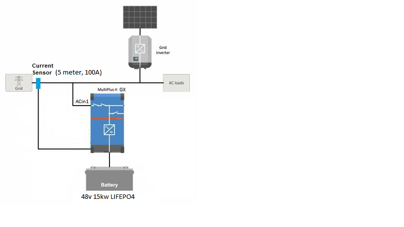
Im setting up a Multiplus II GX , running ESS assistant. My system is wired in parallel configuration, as pictured below. After trawling through many posts on the forum, im still non the wiser if this configuration will work. Some have said you definitely need a grid meter ( et112 ), and some have just used the CT. So ive rolled the dice and went with using just the victron 5 meter 100A CT Clamp. Well, after a lot of mucking around, i haven't been successful to get the Multiplus 2 to behave as it should.

When the MP is booting up from first switch on, it does all the relay tests, and then attempts to connect to the grid. Now, if my AC coupled Fronius Inverter is outputting more than the loads are consuming, ( excess feeding into the grid ) the MP fails to connect to the grid, does the relay test again, and repeats this cycle. However, if the PV inverter is not producing more than is consumed by the loads, (so not feeding back into the grid) the MP will boot up and connect to the grid.

If i put the PV inverter outside of the CT clamp, the MP is happy, regardless of PV generation. But the problem i have then, is the MP wont use the excess PV to charge the battery.

Even though the Fronius sends its generation figures to the MP via TCP, the MP doesnt do anything with those figures. I think the MP has to 'measure' the flow of current by means of a grid meter.

So before I run out an buy a ET112 grid meter, i wanted to hear if anyone has had success with just the CT clamp in a grid parallel system with AC coupled PV.


Running firmware: 3.13 for the GX, 508 for the VE bus.

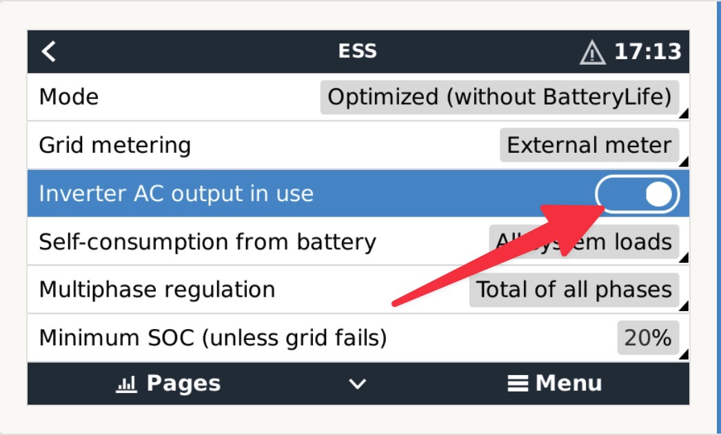
External current sensor 'checked' in VE configure

Feed-in excess PV is 'on'


1704811929930.png


AC PV Couplinggrid parallelct clamp
1704811929930.png (58.4 KiB)
4 comments
2 |3000

Up to 8 attachments (including images) can be used with a maximum of 190.8 MiB each and 286.6 MiB total.

ejrossouw avatar image ejrossouw commented ·

@Cliff76 Some things I will check. Possible faulty CT? CT mounted the correct way around on the positive incoming tail with arrow pointing towards house loads? Is the connector inserted properly? Does the MP system work as intended and discharge in line with the loads when there is no solar? Have you tried when feedin excess is disabled? I never enabled it on systems with grid inverters on the ACIN as per your diagram.

0 Likes 0 ·
cliff76 avatar image cliff76 ejrossouw commented ·

Thanks for the tips @ejrossouw , I double checked the CT orientation, made sure the arrows were pointing toward the load. I turned it around the opposite direction to see what that would do. It does connect to the grid when arrows pointing toward grid, but then the inverter dumps all my battery into the grid, which is not what i want.

When there is no solar, the MP behaves as it should - supplies the loads. It connects to the grid and keep grid set point at about +100W, (despite setting it at +50W ). So the CT appears to be doing something right when there is no solar generation. I will try your suggestion and change the grid feed-in setting to 'off'. See how we go.

The neutral has about 16mv on idle, and about 70mv when the MP is inverting.I would have thought that if the neutral was an issue, then i wouldnt be able to get it to connect in any scenario? All neutrals go back to the main neutral link ( bus bar )..

No errors appearing on the GX. All good there.

Im wondering at this stage if I should do a factory reset on it, and start again. Maybe a setting hasnt taken properly. I used remote VE Configure to set it up, and it seemed to make the setting changes without any problem. Im a bit hesitant when remotely configuring devices. I might try the VE dongle.

Do you think it could be possible I have a faulty MP? Or does it sound setting related?

0 Likes 0 ·
ejrossouw avatar image ejrossouw cliff76 commented ·

Personally I will start with a clean slate and introduce the additional components one at a time. The MP ESS can work just fine with a non compatible grid inverter so start 1. without an IP connection to the Fronius 2. don't enable any feedin etc. settings 3. Ensure the ESS assistant is set to NO inverters on the ACOUT. Using Remote VE.Configure works just fine and I use it all the time. Even for a system 6000kms away ;) While I don't rule out a possibly faulty CT or even MP, it is it not something I have personally encountered in the field. Also, returning a product just to have it returned without the seller finding fault, not fun.

0 Likes 0 ·
cliff76 avatar image cliff76 ejrossouw commented ·
I'll give that a go @ejrossouw . I did try the 'no feed in excess pv', but it didnt seem to make any difference. The only way ive been able to get it to work somewhat is by taking the PV inverter feed out of the CT clamp ( only keeping loads and the MP in the clamp ). The MP will connect to the grid, I can discharge battery into loads, though it wont automatically charge the battery with PV. I can do a schedule charge whilst there is PV, and it will charge the battery. Not ideal, as it becomes a very manual process.

I also double checked the 'No PV on AC out' in the ESS assistant in VE Config. Definitely on 'No PV on AC Out'

It's been a really frustrating exercise to say the least. Totally get what your saying if unit goes back and the seller doesn't find a fault with the unit. Which is why im exhausting all avenues before it goes back.


I'll factory reset it tomorrow, and start from scratch, making sure the Fronius is off the network first..
0 Likes 0 ·
2 Answers
Alexandra avatar image
Alexandra answered ·

@Cliff76

You shouldn't need a meter. I have seen many systems with fronius and no meter. So in terms of function of the Victron system that is not the issue. The system will throttle the PV inverter and everything correctly.

Check your line neutral connections. MP2 is known for not liking anything (even slightly) incorrect there. Any current/voltage on neutral?

I assume there are no errors on the GX?

15 comments
2 |3000

Up to 8 attachments (including images) can be used with a maximum of 190.8 MiB each and 286.6 MiB total.

cliff76 avatar image cliff76 commented ·

Thanks for the info @Alexandra .

The neutral has about 16mv on idle, and about 70mv when the MP is inverting.I would have thought that if the neutral was an issue, then i wouldnt be able to get it to connect to the grid in any scenario? All neutrals go back to the main neutral link ( bus bar ).. Everything seems right and tight there.

No errors appearing on the GX. All good there, too

0 Likes 0 ·
Alexandra avatar image Alexandra ♦ cliff76 commented ·

It depends. Once looked in on an install where one circuit in the household had them switched over and that caused and issue - but only sometimes. So there was hair pulling when trying to work it out.

What happens is if a control relay such as the ground relay has a bit of current over it is the relay stays energised then the relay tests fail.

So check on the GX and see if what the relay test says.

0 Likes 0 ·
cliff76 avatar image cliff76 Alexandra ♦ commented ·

Sounds like a real curly one @Alexandra .

I can get the MP to connect to the grid if the Fronius is left out of the CT clamp.

When the Fronius is in the CT clamp, together with the MP and loads, that's when all my problems start. As soon as the Fronius starts to produce over and above the load demand, then the MP will disconnect from the grid. I feel something is screwed up with the metering (I think).. It's like the MP sees the outgoing current from the Fronius as an error. Ive tried the setting 'no feed in excess PV' and also 'Feed in excess PV ' . Both settings didn't make any difference..

The ESS relay check reports ok.

Really scratching my head over this one..

0 Likes 0 ·
Alexandra avatar image Alexandra ♦ cliff76 commented ·
@Cliff76

Hmmm. Have you set on the inverter to AC output not in use?

Batteries set to keep charged?

Is there a shift in frequency at all in the system?

0 Likes 0 ·
cliff76 avatar image cliff76 Alexandra ♦ commented ·

@Alexandra , i can only see these settings for the PV inverter:

Position:

  • Ac Input1
  • Ac Input2
  • Ac Output


I have this set to AC input 1.

Batteries are set to 'Optimized without BatteryLife'

No frequency shifting or throttling of the PV inverter is occurring.

0 Likes 0 ·
Alexandra avatar image Alexandra ♦ cliff76 commented ·

@Cliff76

I was thinking about the logic of the installation

AC PV is feeding loads, but the inverter has no loads. So your gut feeling of it not using the information from the AC PV is correct. It needs a way to meter what is going on.

A further read in the manual reveals you are correct you need a grid meter for the AC PV to be on the input.

When you have done that then the option to disable the AC output also becomes available.

0 Likes 0 ·
cliff76 avatar image cliff76 Alexandra ♦ commented ·

That's how i read it as well @Alexandra . I read it as an energy meter is required. Though looking around on the forum, it seems a lot of people have a setup with just the CT clamp. I wonder if it may have been possible at one stage with older firmware? Im currently running the most up to date firmware, so there may have been some changes. Maybe an energy meter is required now?..


What's interesting is how my system is set out on VRM.. It does have the PV inverter ( graphically ) on the output side of the MP. But my GX display has the PV inverter connected to the bottom of the MP..

Its all very weird, almost like a software mismatch somewhere.. Or if not a software issue, then maybe i do need to purchase an ET112 so it can 'see' the energy flow (to and from the PV inverter) to the grid

1705037333490.jpeg

charging only because i have a schedule charge set..


1705037466186.jpeg


0 Likes 0 ·
1705037333490.jpeg (75.5 KiB)
1705037466186.jpeg (52.4 KiB)
Alexandra avatar image Alexandra ♦ cliff76 commented ·
@Cliff76

I am going to ask support and find out. None of my AC PV are on new firmware.or hardware.

1 Like 1 ·

Hi @Cliff76,

Can you please double check to make sure this setting in the ESS menu of your GX device remote console is set to OFF?

(I know it shows as ON in my screenshot, it should be the opposite for your system configuration).


EDIT - Alex just informed me that this setting isn't available when using the CT (and not an External meter), I'll try and find out why that is the case, but unfortunately it would seem that for now the easiest solution would be to install the external energy meter for a known working solution.


cleanshot-2024-01-15-at-171313.jpg

0 Likes 0 ·
Alexandra avatar image Alexandra ♦ Guy Stewart (Victron Community Manager) ♦♦ commented ·
@Cliff76

It is important to set the "External current sensor" setting in VEConfigure.

Just wondering if you had done that?

0 Likes 0 ·
cliff76 avatar image cliff76 Alexandra ♦ commented ·
@Alexandra Hi Alex, I did try this setting. I tried it with it set to on, and off, but it didnt make any difference. I wondered if this setting was for the external Current Sensor ( plugged into an aux input ), not the Current Clamp? I'm not sure. But for my system, it didnt make any difference. Thanks for trying to help me solve this.
0 Likes 0 ·
Alexandra avatar image Alexandra ♦ cliff76 commented ·
@Cliff76

I'm VE Configure not on the GX. So it is a setting done with the MK3 on the inverter.

0 Likes 0 ·
cliff76 avatar image cliff76 Guy Stewart (Victron Community Manager) ♦♦ commented ·
@Guy Stewart (Victron Community Manager) Thanks for your help with this, Guy. Yes, Alex is correct. That setting is only available when Grid metering is set to 'External'. I might have to bite the bullet and try an ET112
0 Likes 0 ·
If possible I would suggest trying the new Victron brand Energy Meter instead of the ET112. It has a much faster response time.
0 Likes 0 ·
cliff76 avatar image cliff76 Guy Stewart (Victron Community Manager) ♦♦ commented ·

@Guy Stewart (Victron Community Manager) .. Thanks Guy, i might look at the VM-3P75CT. Might be a bit of overkill as i only have single phase. But i might be able to make use of the remaining two ct's for other load measurement..

0 Likes 0 ·
atebee avatar image
atebee answered ·

If you are using a CT then this is not an "External" meter per the settings. External refers to meters such as the ET112.

The unit has an internal CT, by connecting your own CT to the terminal block you bypass it. But it's still the MPII doing the metering rather than an external device.


screenshot-2024-01-09-21-48-46-64-40deb401b9ffe8e1.jpg


1 comment
2 |3000

Up to 8 attachments (including images) can be used with a maximum of 190.8 MiB each and 286.6 MiB total.

cliff76 avatar image cliff76 commented ·
Thanks @Atebee , i do have the system set to 'inverter/charger' for grid metering. If set to 'external' the MP will go into 'passthrough' mode because it cant 'see' an external meter connected.
1 Like 1 ·