question

Alex Pescaru avatar image
Alex Pescaru asked

Multi RS temperatures and fans...

A question for the hardware/software designers at Victron...

@Guy Stewart (Victron Community Manager)

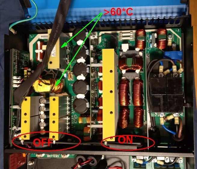
I know that the last software version involved some fan improvments, but is it normal for the left fan to not operate during grid battery charging?

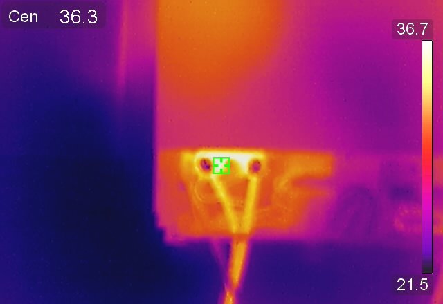
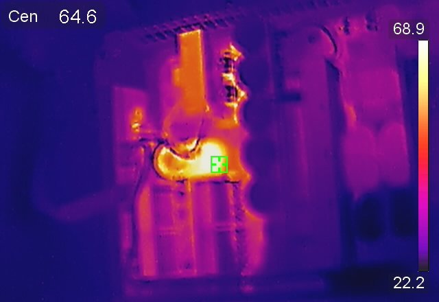
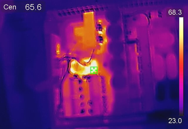
Charging the battery with a maximum limit of 40A, the left transformer and the transistors on the radiator above it get to about 66 degrees Celsius, read with a thermal camera.

And also the left side of the inverter gets pretty warm because of the above.

See below picture.

temperatures.jpg

Multi RS
temperatures.jpg (152.2 KiB)
2 |3000

Up to 8 attachments (including images) can be used with a maximum of 190.8 MiB each and 286.6 MiB total.

9 Answers
Guy Stewart (Victron Community Manager) avatar image
Guy Stewart (Victron Community Manager) answered ·

Hi @Alex Pescaru,

The two fans inside the MultiRS (DCDC and DCAC) are controlled independently with the purpose to minimize the fan noise when only cooling one is required.

Fan speed is based on a combination of current and temperature thresholds


For the DCDC fan:
Idc < 45A and heatsink < 40°C => Fan is OFF
Idc > 45A and heatsink > 40°C => Fan is ON
Heatsink > 55°C => Fan is ON

Your numbers appear ok and normal.

There are some hotspots with a higher temperature than measured on the heatsink, but they remain well below the allowed limits. That's why the fan is enabled at a lower temperature for larger currents.

It is not recommended to do any modifications in this situation.

6 comments
2 |3000

Up to 8 attachments (including images) can be used with a maximum of 190.8 MiB each and 286.6 MiB total.

Alex Pescaru avatar image Alex Pescaru commented ·
@Guy Stewart (Victron Community Manager)

Thank you and your team very much for your effort to explain it to me in detail.

This kind of technical details are an invaluable peace of mind for me because now I know what to expect and why.

And probably for anyone like me who likes to know more about these great products and the line of thought that lead to their conception.

Is there any service manual where I can learn more about their functioning?

For sure it will be a great resource for the technical inclined people and for sure it will make these people (and others too) hooked forever with your products.

Thank you again!

0 Likes 0 ·
Guy Stewart (Victron Community Manager) avatar image Guy Stewart (Victron Community Manager) ♦♦ Alex Pescaru commented ·

As far as I know there isn’t a service manual for the RS yet. There are internal documents and resources, and they are still being actively updated, as the product is.

The RS R&D team is under a lot of pressure to get the feature set up to par (ESS, parallel, et al), support new products like the Victron Energy meter, and improve performance (see RS 1.16 beta shade improvements in modifications space).

Over time both through questions like yours, and enquires through dealers and repair centres more technical information will created.

1 Like 1 ·
Alex Pescaru avatar image Alex Pescaru Guy Stewart (Victron Community Manager) ♦♦ commented ·

@Guy Stewart (Victron Community Manager)


Thank you again for the feedback.

Being new to your products and this community, I've spent quite few hours reading various threads about various issues. Almost all about RS.

Without bragging too much, my over 25 years experience in the area of both software/firmware and hardware design with various microcontrollers are yours if you want them. In other words I want to help with anything if it's possible and you want it.

Thanks again!

0 Likes 0 ·
frankmsc68 avatar image frankmsc68 commented ·

@Guy Stewart (Victron Community Manager) hi there...might be another point to put on the list of possible improvements...to be able to turn fan(s) on constantly....thanks,Frank

0 Likes 0 ·
Guy Stewart (Victron Community Manager) avatar image Guy Stewart (Victron Community Manager) ♦♦ frankmsc68 commented ·
I’ll mention it to them as a feature request, but no promises beyond that.
1 Like 1 ·
Alex Pescaru avatar image Alex Pescaru commented ·

Hi @Guy Stewart (Victron Community Manager)

Merry Christmas !

Thanks again for the info, but can I ask you one more thing?

Can you also please find out the logic behind the ACDC fan functioning too?

Thank you in advance !

0 Likes 0 ·
Guy Stewart (Victron Community Manager) avatar image
Guy Stewart (Victron Community Manager) answered ·

This change has now been implemented in 1.16 beta 05 here - https://community.victronenergy.com/questions/255822/rs-shade-performance-testing-v116-beta-05.html

It is hoped to make a public release next week.

1 comment
2 |3000

Up to 8 attachments (including images) can be used with a maximum of 190.8 MiB each and 286.6 MiB total.

Alex Pescaru avatar image Alex Pescaru commented ·

Hi @Guy Stewart (Victron Community Manager) , @mvader (Victron Energy) , @Thiemo van Engelen (Victron Energy staff)

Thank you and all Victron's developers a lot for everything !!!

Thank you for listening to us, users !!

Alex

0 Likes 0 ·
Alex Pescaru avatar image
Alex Pescaru answered ·

@Guy Stewart (Victron Community Manager)

Please guys, a little bump on this...

How can I enable both fans when charging from grid? I don't mind the sound, just the proper, cool, functioning...

I appreciate that the right fan must function, because of the AC/DC converter that needs to generate DC bus voltage.

And I also believe that the left upper transistors are used as a Buck converter in order to lower the DC bus voltage to the battery charging voltages, voltages that are passed with the use of the reverse diodes from the DC/DC converter "H bridge" transistors directly onto the battery.

But, as I was saying in the previous message, during functioning, the DC/DC transformer, the buck converter transistors and the "H bridge" transistors are becoming quite hot. Over 65 degrees.

Problem that could be solved just by enabling the left, DC/DC fan, how you name it on the board, which in this moment is off all the time during charging from grid.

Is the fan driver transistors capable to handle/drive both fans simultaneously? Because I can try to put both fans in parallel to work simultaneously...

Please help.

Thank you!


1 comment
2 |3000

Up to 8 attachments (including images) can be used with a maximum of 190.8 MiB each and 286.6 MiB total.

I’ll ask, but it might be a while before we get a response due to the holidays.


65 degrees is hot, but not yet something to worry about and within component spec.

0 Likes 0 ·
wanek avatar image
wanek answered ·

Maybe you can try to downgrade to the prev. firmware version until someone looks into this and test if both fans work properly? Probably now with the holiday season will take long time for them to solve the issue.

1 comment
2 |3000

Up to 8 attachments (including images) can be used with a maximum of 190.8 MiB each and 286.6 MiB total.

Alex Pescaru avatar image Alex Pescaru commented ·
@wanek

Good point and now that we have some references from Guy about temperatures and currents, I can make some comparisons.

0 Likes 0 ·
Alex Pescaru avatar image
Alex Pescaru answered ·

Hi @Guy Stewart (Victron Community Manager)

I am bringing this back because I've saw that rarely, now in winter, the charging current is above 45A.

And the left side of the inverter, without the fan starting, is quite warm, if not hot.

I know, I keep insisting on this but take into account the followings:

1. The ACDC fan (right one) can't influence the airflow on the left side of the inverter (DCDC side), because of the ACDC board, so the air is quite static on the left side, the DCDC side.

2. All the electrolytic capacitors, DC bus electrolytic capacitors and mostly battery/ripple capacitors are on the HOT, left DCDC zone. Especially the battery capacitors, which are surrounded by hot things: left-right H bridge transistors, up - DCDC transformer. The battery capacitors must handle the battery ripple and must supply energy during transitory periods when the H bridge FETs are switching.

3. From what I saw, the capacitors are 85 degrees Celsius rated, not 105 degrees Celsius rated.

This inverter is a relatively new one (2-3 years) and the capacitors didn't have enough time to age, but all of the above will lead to an accelerated capacitor drying process and soon we will wonder why the DCDC FETs are starting to explode, especially for the older equipments.

The PCB industry is putting a lot of interest in the system design thermal profile and for sure the left lower side of the inverter, the H bridge side, is quite a danger zone for components, especially for capacitors. And you can easily solve this by starting the DCDC fan earlier.

For sure, if you ask the owners, most of them will say that they prefer an equipment that is noisy, cool and last longer than an equipment that is quiet, hot and last shorter.

So, please, please, pretty please, as you've done with the ACDC fan logic that you've started it earlier on the 1.15 version, please lower the limit on the DCDC fan to 35A, even 30A instead of that 45A, because all the components will thank you later. And us, the owners of the equipment.

Or give us some options to set it according to our environment, some option in the settings to allow us to select some cooling profiles (Economy, Normal, Cool, 100% ON), like you find on the PC motherboard BIOS for fans.

Thank you a lot for listening!!

2 |3000

Up to 8 attachments (including images) can be used with a maximum of 190.8 MiB each and 286.6 MiB total.

Alex Pescaru avatar image
Alex Pescaru answered ·

Hi developers,

@Guy Stewart (Victron Community Manager) , @mvader (Victron Energy) , @Thiemo van Engelen (Victron Energy staff)

I am coming back with proof of heating zones. See the pictures below and the temperatures.

See how cool is the ACDC side compared with the DCDC side...

Take into account that the hot zone in the battery terminals zone are not because of the bad connection, but the PCB area that is hot because of the H bridge transistors.

I realize now that can be cases, like myself, where the PV power isn't enough for hitting that 45A limit you've set in this moment.

So the inverter, if the battery bank will be bigger, will functions for hours, just below that 45A, without ventilation on the DCDC side, and allowing this way for the temperatures in the DCDC area to rise quite high.

I know, at some point maybe the temperatures will be high enough (55 degrees) and the DCDC fan will start, but for sure the electrolytics in that area are "crying" out loud and gasp for cool air... And all of them (electrolytics) are in that area... Both DC Bus and ripple capacitors.

Please, please, lower a bit that 45A limit.

I saw that the ACDC fan starts, slowly, when the PV generated power is over 1000W. Here for the DCDC zone, a 45A at 50V is over 2200W.

Please balance a little the power that came from the ACDC side to the power on this DCDC side. Start the DCDC fan at at least 1500W, which means 30A.

Please, please, pretty please, start the DCDC fan at at least 30A. It won't be much noisier than now.

Many thanks to you!

1.jpg

2.jpg

3.jpg


1.jpg (23.0 KiB)
2.jpg (27.3 KiB)
3.jpg (28.6 KiB)
2 comments
2 |3000

Up to 8 attachments (including images) can be used with a maximum of 190.8 MiB each and 286.6 MiB total.

Hi @Alex Pescaru,

Appreciate the level of detail.

I passed on your previous post a couple of days ago and the developers agreed to include a variation in the next firmware test to reduce the DCDC fan activation current to 30A to see the results. I'll try and post back here when it's ready, but also please keep an eye out in the modifications space.

2 Likes 2 ·
Alex Pescaru avatar image Alex Pescaru Guy Stewart (Victron Community Manager) ♦♦ commented ·

Thank you a lot @Guy Stewart (Victron Community Manager) !

It's all that I asked!

I will keep an eye out for this!


0 Likes 0 ·
beat avatar image
beat answered ·

Thank you @Alex Pescaru for looking closely at heat and documenting it!

@Guy Stewart (Victron Community Manager) @mvader (Victron Energy) @Thiemo van Engelen (Victron Energy staff) From a heat and ventilation flows and ventilation noise decoupling, the electronic design of all Victron equipment could sure be improved, separating better heat-sensitive-aging components like electrolytic capacitors from heat-generating and -supporting ones.

Also the need for venting and noise level could be significantly reduced with cheap damping vents fixing and aerodynamic "flow tunnels" before/after vents. This fantastic publication has really interesting suggestions for significantly improving fan flow and noise through fix damping and great flow design, applicable to any venting actually (sorry in German, but images and graphs are self-explanatory mostly): Really worth looking at it (for me it was "aha, easy!" moments!) https://www.aramis.admin.ch/Default?DocumentID=63782&Load=true

2 comments
2 |3000

Up to 8 attachments (including images) can be used with a maximum of 190.8 MiB each and 286.6 MiB total.

Alex Pescaru avatar image Alex Pescaru commented ·

Hi @beat

I was thinking for some time using things like this in the link below to see if the resonance fan noise lowers.

https://www.ebay.com/itm/184514566565

https://www.ebay.com/itm/183862738736

0 Likes 0 ·
noted - thank you!
0 Likes 0 ·
Alex Pescaru avatar image
Alex Pescaru answered ·

Hi developers and All,

@Guy Stewart (Victron Community Manager) , @mvader (Victron Energy), @beat

I tried some silicone rubber mounts for one of the fans, the ACDC one.

I had some left from some Noctua fans. See below the picture.

Boy, what a change! The fan is just whispering now, without any whining at all!

Especially at lower speeds, where the whining was amplified by the metal case probably because of the low PWM.

Maybe you can try them on the future hardware release of Multi RS.

Thanks,

Alex

fanmounts.jpg


fanmounts.jpg (28.3 KiB)
1 comment
2 |3000

Up to 8 attachments (including images) can be used with a maximum of 190.8 MiB each and 286.6 MiB total.

frankmsc68 avatar image frankmsc68 commented ·
Hi Alex,thanks just ordered them as well.....
0 Likes 0 ·
beat avatar image
beat answered ·

Awesome! Thank you for the feedback, @Alex Pescaru ! They are very cheap and actually win mounting time as they replace manual screws.

@mvader (Victron Energy) And for the still loud MP-II fans too!

Actually for all your fans of all your produects that are actually screwed directly to chassis!

And possibly a rugged version for the torus transformers that are very loud too. ;-)

2 |3000

Up to 8 attachments (including images) can be used with a maximum of 190.8 MiB each and 286.6 MiB total.