question

Gavin avatar image
Gavin asked

Multiplus-ii Parallel - ESS not hitting Grid Setpoint

Hi All,

Background

I have been running a single Multiplus-II 48/5000 (HQ2203) for the last 12months with ESS enabled, and its been working great. Charges overnight, and during the day it keeps grid usage close to 0 Watts.

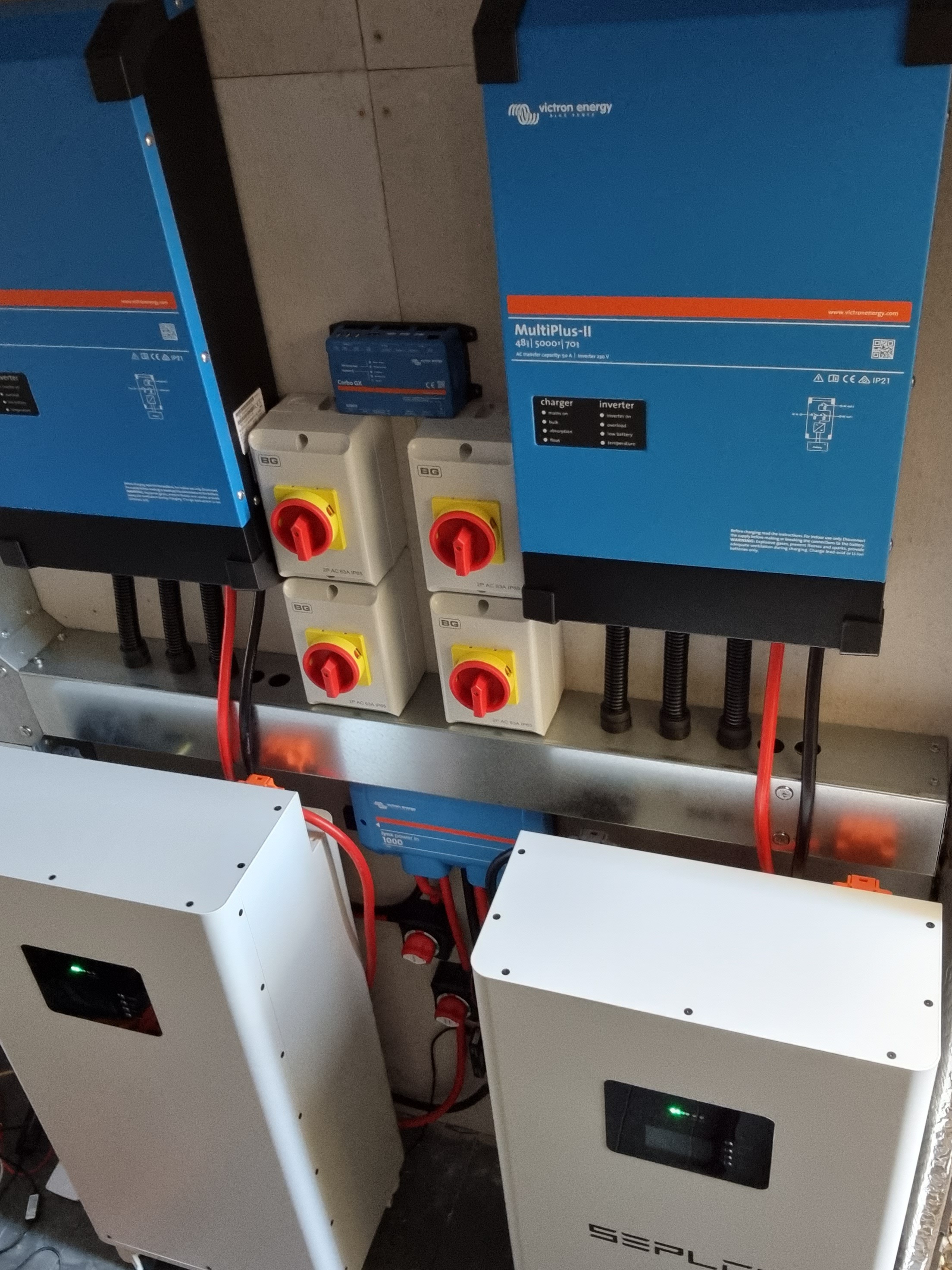
I purchased a 2nd Multiplus-II 48/5000 (HQ2237) earlier this year, and finally connected it last week.

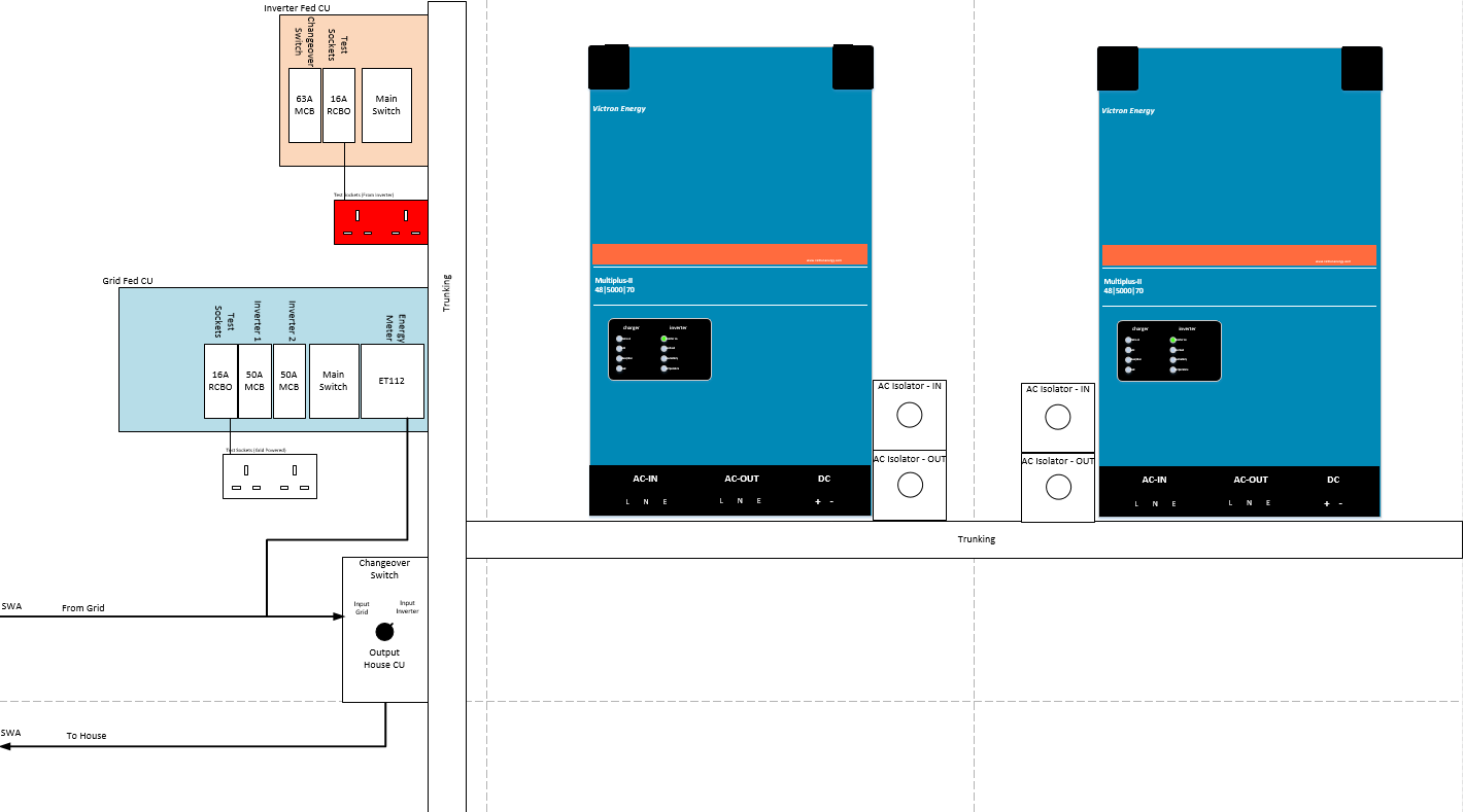
The units were installed with same length cables (Both AC & DC), and the units have been configured as Parallel using QuickConfigure. Both have the same settings and ESS Assistant applied.


The Probem

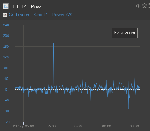
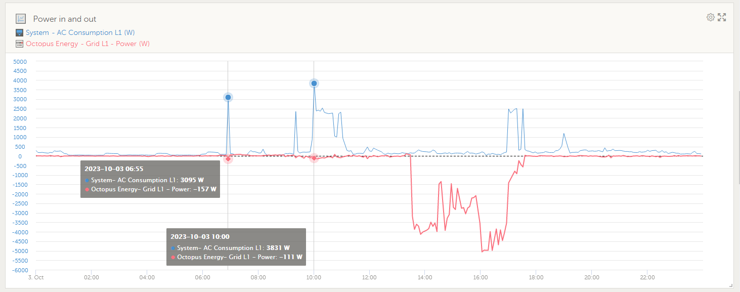
ESS is unable to reach the SetPoint (0 Watts).

The CerboGX shows that when AC-OUT (The House) is consuming 500W, ESS seems to discharge too much from the battery and therefore exports 150W - to the grid.

This figure drifts further when the load increases.


Thoughts

  1. Could the build dates of my Multiplus-II's be incompatible?
  2. Is the 1.2Meter x 10mm2 cable too low resistance?
    1. I used the same cable on AC-IN and AC-OUT
  3. Is the 0.6Meter x 50mm2 DC Cabling too large?


I have searched the forum and found a couple of similar posts, but most do not have solutions to this issue.

ESSmultiplus in paralleless grid setpoint not reached
2 comments
2 |3000

Up to 8 attachments (including images) can be used with a maximum of 190.8 MiB each and 286.6 MiB total.

Michelle Konzack avatar image Michelle Konzack commented ·
Since I plan to install up to three MulitPlus-2 24/5000 in parallel, I made already in the right size, always the maximum lenght needed, even if my AC wires look a little bit funny with the lenght.


However, the Tripple DC Fuse Box NH3 (i can pull out the fuses in parallel) are on the left and use 140cm long H01N2-D 70mm2 and the AC out 140cm long H07Z-K 4mm2.


5000VA / 230V = 21,7A

hence a 2,5mm2 would be fine, but in an overload situation the cable are too small. Do not use a smaller then 4mm2 for the AC out.


One thing I have discovered is, that if the AC out wires (Phase and Neutral seperately) are rolled up and NOT stretched out, then the MultiPlus works more smouth.


My first MultiPlus-2 was bought in 2022/10 and the second 2023/05 (but a friend loaned me his one for testing and it was manufactured on 2021 and worked too)


Since the system is Off-the-Grid, I do not use ESS.

0 Likes 0 ·
Gavin avatar image Gavin Michelle Konzack commented ·
Thanks for the response.

I need to take some measurements with a multimeter and try to get an understanding of what is happening.

Because I am ongrid with the whole house connected to the AC-OUT's there is the potential for the house to draw the maximum 100A from the grid (50A per Multiplus) So i sized the cables as 10mm2.

Maybe 6mm2 cable could still be enough, and add a little resistance to overcome the inbalance from the multiplus's.


0 Likes 0 ·
5 Answers
iammotorhomeless avatar image
iammotorhomeless answered ·

How are you monitoring your grid point
I use the Energy Meter ET112
it never sits on 0 watts. up and down by about 20 watts with the grid fluctuations

that said my average inmport is less than 150 watts per day. so it does not bother me much

how big is your battery bank ?

2 comments
2 |3000

Up to 8 attachments (including images) can be used with a maximum of 190.8 MiB each and 286.6 MiB total.

Gavin avatar image Gavin commented ·
Sorry for delay in replying.

I have an ET112 for monitoring the Grid.


When running a single Multiplus with ESS, it is able to keep the ET112 very close to Zero. Typically it will hover between -30W and +30W.


The moment I introduced a second Multiplus, the ESS would discharge too much power from the battery, leaving an excess of power being exported to the Grid. It appears too be approx 25-30% extra being discharged.


0 Likes 0 ·
Gavin avatar image Gavin commented ·
Battery bank is 28Kwh
0 Likes 0 ·
sgrigor1 avatar image
sgrigor1 answered ·

1. The multiplus II inverters should be OK. Try to asign the master role to the new one. For me it helped but I have two years differences between them.

2. 10mm2 is too much and ofcourse the resistence is low. 4mm2 is good enough for 5000VA. Hope you used H07 wires, CYY is not good. Can you share the connection schematic, you din't provide too much on how you conected the invertos to grid and load.

3. DC cable should be OK, 50mm2 means about 150A. Do you have more? Not the DC is the issue.

4. Disable the LOM detection on your grid code. If you're facing the same issue then I recommend you to replace the AC wires to 4mm2, H07, 1.2m length is OK. Do a test with 4mm2.

Try 50W on ESS setpoint.

5. Check the ground continuity between both invertors and AC-IN, AC-OUT.

6. Check the ground, measure with multimeter the ground agains NULL, the difference should be low.


Post more info on your ESS configuration, upload the VE Configurator file check it offline.

Any little detail matter in this parallel connection.

9 comments
2 |3000

Up to 8 attachments (including images) can be used with a maximum of 190.8 MiB each and 286.6 MiB total.

Gavin avatar image Gavin commented ·

Thanks @sgrigor1 ,

Here is a diagram I put together:

homesetup.png


There is a manual changeover switch to allow me to bypass the Victron installation, and connect the house directly to Grid during maintenance/failure.

I just noticed that I am using a 63A MCB between the combined AC-OUT's and the Manual Changeover switch, so 63A is my maximum current which the house can consume. Perhaps I should look to replace my 10mm2 cabling with 6mm2 or 4mm2.


I'll first test with the newer Multiplus-II being the master. I am certain that I had the older unit as master last week when I tested.

0 Likes 0 ·
homesetup.png (42.7 KiB)
iammotorhomeless avatar image iammotorhomeless Gavin commented ·

that looks just like mine

iammotorhomeless-2xmp-ii.jpg

but I have an RS in there.
battery is BYD 16kWh, on the floor under fuse box.

with short runs of cables, you have to get the size right. (bigger is not always better)

0 Likes 0 ·
Gavin avatar image Gavin iammotorhomeless commented ·

Yes, I think the cables sizes may be my issue.

I am hoping that making the newer Multiplus the master will help, but think i'll need to replace the AC-IN/AC-OUT wiring with 6mm2, or maybe even 4mm2.


Here is a pic of mine installed.

Was running VenusOS on RPi at the time, but now running on the CerboGX and Touch Screen.

installed.jpg


-1 Like -1 ·
installed.jpg (1.6 MiB)
iammotorhomeless avatar image iammotorhomeless Gavin commented ·

with mine... the Lynx distributor. I have the batterys on the two outside connections
my thought is that if the two Multiplus feeds are in the middle close to each other it reduces the resistance between them
and allows easy flow to either battery. if one needs to draw or charge more than the other.

secondly. all those DC switchs. I don't have any (just the fuses in the Lynx)
you don't need one between the Lynx and the Multiplus, you are just adding resistance points.
And with my BYD, I can just press a button to turn it off.
Your Seplos should be the same

0 Likes 0 ·
iammotorhomeless avatar image iammotorhomeless Gavin commented ·

ok. I have just had a closer look at mine.

on VRM it shows an export from the battery when supplying a load
but on my Smart meter the export is not there.

Is it just to small and short to be seen on the Smart meter, but the Victron gear still shows it ?

export-from-battery.png honestly, for me it's not an issue.
but if you were not aloud to export anything. it might be

0 Likes 0 ·
Gavin avatar image Gavin iammotorhomeless commented ·

With a single Multiplus-ii my setup would hover rather close to 0 Watts

singlemulti-ess-setpoint-0watts.png


After adding the 2nd Multiplus-ii we shoot past 0watts and keep exporting continuously.

parallelmulti-ess-setpoint-0watts.png

0 Likes 0 ·
Michelle Konzack avatar image Michelle Konzack Gavin commented ·
If you have 50A, then you need at least 6mm2
0 Likes 0 ·
sgrigor1 avatar image sgrigor1 Gavin commented ·

Ok, still do more tests before to change the cables. For example, try to load the invertors to 8-9KW and measure the current on each AC-OUT segment. Which is your maxim load of the system 20KVA? Measure the current also at this load. You should have little differences between segments.


If you what to use a big load, consider large wires sections, even 10mm2 but increase the length. I gave you an example from my case where the max load is 8-9KW, so 4mm2/1.6m is OK in my case.


Did you enabled the BMS communication with the invertors? Pay attention to the configuration in VEConfigurator.

0 Likes 0 ·
Gavin avatar image Gavin sgrigor1 commented ·
Yes the two Seplos packs are linked, and the master pack is connected to the CerboGX.


I should be able to do some tests by disconnecting AC-OUT and setting ESS GridPoint to -10,000Watts. With no fluctuating load it should be easier to measure & compare the current exporting form each inverter.

1 Like 1 ·
nickdb avatar image
nickdb answered ·

Generally, two parallel inverters will be more fluid around the setpoint but large differences and feeding back is usually using the old one as master, not the new one, as well as too short/thick AC cabling.

Don't undersize the wiring, work out what you will realistically use, and remember that the transfer switch is rated to 50A and the inverter can peak above 5kVA.

1 comment
2 |3000

Up to 8 attachments (including images) can be used with a maximum of 190.8 MiB each and 286.6 MiB total.

Gavin avatar image Gavin commented ·
Thanks for the response @nickdb ,


I think you maybe correct about the older Multiplus being the master. I selected that one as master because the MK3 was already plugged into it. I'll have another test with the newer model as the master and will check the outcome.


I have a 100Amp connection to the grid, so I sized the cables to allow the House to be able to use the whole 100Amps if needed. That was the reason I went for parallel Multiplus-ii to get the 2x50A Transfer switch. 50A was not enough when we are charging the batteries and charging our Electric Vehicle during the offpeak night tariff.

0 Likes 0 ·
dariusdiy avatar image
dariusdiy answered ·

I have a similar issue as the one related above. Had a Multiplus 2 with PV inverter on input and ET340 energy meter, and everything worked just fine tracking the set grid point of -10W.

After installing a second parallel Multiplus II, even though the output load is balanced between the inverters, when the PV inverter starts to generate, the grid setpoint almost mirrors the Output power, eg. if output on critical loads is ~1000W it would be pushing to the grid ~700W from the battery (since the PV inverter just started generating in the morning).
This issue continues all day regardless how much the PV inverter is producing and it also continues at night untill a load of ~2000W is applied for a few seconds, then the grid goes back to the set -10W. If I let just the DC coupled PV via the MPPT 250/100 this issues does not happen.


Any Ideas why/ any solution?

(GX firmware v3.10, Multiplus II running firmware version 506)

P.S. if I reconfigure to a single Multiplus II (regardless of which of the two), again the problem goes away

2 |3000

Up to 8 attachments (including images) can be used with a maximum of 190.8 MiB each and 286.6 MiB total.

sgrigor1 avatar image
sgrigor1 answered ·

You have some suggestions above. Did you tried them? Try also to disable LOM on both invertors on grid code.

1 comment
2 |3000

Up to 8 attachments (including images) can be used with a maximum of 190.8 MiB each and 286.6 MiB total.

dariusdiy avatar image dariusdiy commented ·

Yep, tried all of the above and more without any luck, tried swapping the ET340 for a CT sensor, same issue. Same to be told, about disabling LOM or trieing different grid codes no change. The only 2 "solutions" discovered are use only DC PV, or use just one Inverter (beats the purpose of paralleling).
I will try in a couple of days moving my inverter on the PV OUT side with the obvious changes in wiring , assistants and first of all seeing if it support frequency shifting (GROWATT MIN 6000TL)

0 Likes 0 ·