I plan to use an autotransformer to step up from 120v to 240v for a 240v multiplus. I will sometimes have 240v (50 amp split-phase) shore power available and will bypass the autotransformer. Do I need to isolate the incoming 240v from the output of the autotransformer? When 240v power is present there will be no 120v connected to the input side of the autotransformer.
asked
Autotransformer bypass wiring question
You should be okay doing that. However, if you have 240V on the transformer, the 120V (center tap) will be energized. You need a way to make those wires safe.
You could also elect to open the breaker on the unit when you're not using it, although I don't care for that plan too much.
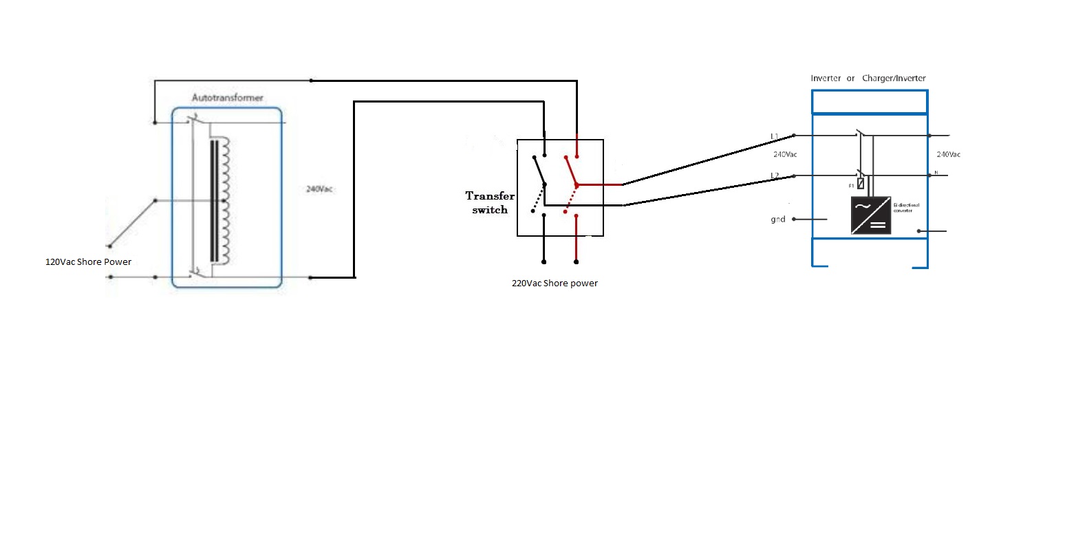
Thanks again for the helpful reply. I hadnt thought about the center tap being energized, autotransformers are new to me. Perhaps a big 3 position rotary switch before the Multiplus to select between the autotransformer output or the 240v shore line.
Maybe draw a picture of your plan and post it here. What I was imagining you were going to do wouldn’t work with a switch there, but you might have a better idea.

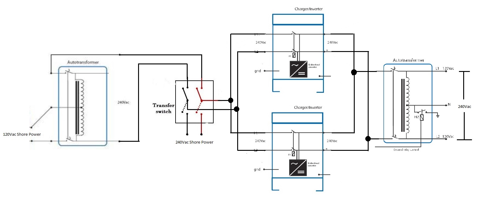
Ah, that looks pretty promising!
So I have a few random thoughts for you to consider:
1) The double-pole breaker (100A) on the AT doesn’t open the neutral tap, so you’re probably right to wire your top wire there to the “other side” like you’ve drawn. You’ll see what I mean when you have the actual unit in your hands.
I haven’t used an AT in this direction (shore step-up), but if the breaker trips on the AT, ideally you’d fully isolate the unit and have no chance of the inverter backfeeding the AT. You’ll set it up so that it doesn’t do that by default in software, but the mechanical protection here is a bonus.
2) I think I forgot to mention this in your other question, but one issue with step-up is that you want to make sure you are okay with the shore current limit minimum on the Quattro when it is in assist mode. That limit will be doubled via the step-up. I believe the minimum for Quattro 5000/48 is currently 5.8A, so your 120V shore limit minimum would be about 12A.
Also, you might check the recent threads on here about issues with shore current minima and make sure you (and/or your dealer) feel comfortable with it. It would suck to build this whole setup and then not be able to charge properly on a standard 15A or 20A outlet.
3) I discovered another issue after I started living in my RV for real. NEC now allows RV parks in the USA to pull two legs off a three-phase, 120deg feed to make the 240V 50A poles. This means that those poles are actually 208V nominal. They are 120V between L1 and N and between L2 and N, but 208V L1 to L2.
On top of that, of course, the 208V might sag to 200V when it is hot outside and everyone is loading up the grid.
And that means your split-phase output on the other side could be as low as 100VAC! Depending on what loads you have, this could be an issue, and you may have to switch to your 120V config in these cases.
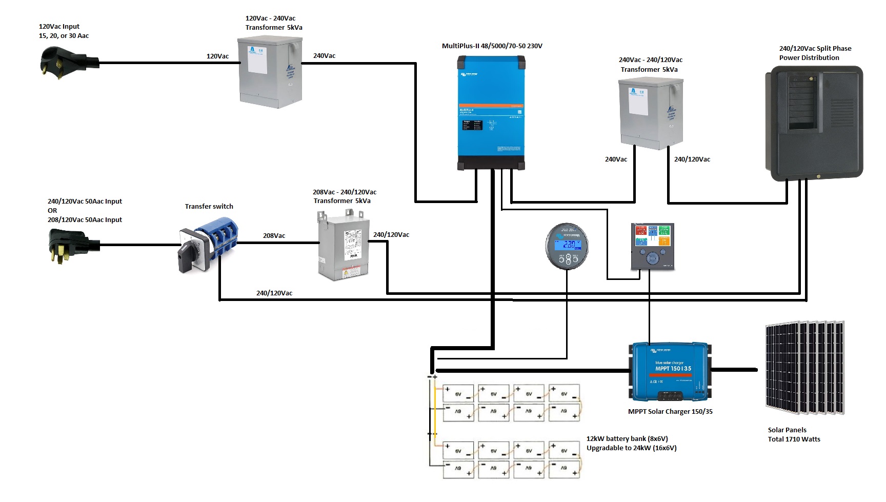
This has been quite a learning experience. After doing a ton of research and reading including the points you raised I have gone through several different designs. Achieving the flexibility and capacity I want without breaking the bank has been challenging.
I believe I have found an elegant solution that allows me to accept 120Vac, 240/120Vac, and 208/120Vac shore connections while always supplying 240/120Vac split phase power to my rig. Using a single Multiplus 2 inverter keeps the shore current minimum low (3.9A x2 for the transformer makes 7.8A) I found industrial transformers with higher ratings for less money to use instead of the Victron autotransformers.
I also realized I was overestimating how much inverter capacity I need because I will always be supplying shore or generator power for assist when using heavy loads, with solar power keeping the batteries charged. Obvious in retrospect but I'm learning as I go.
Similarly I played with transfer switch setups to route shore power through one of 3 circuits depending on voltage (120,240,or 208) to the Multiplus at 240Vac, however this was unnecessarily complex and prone to user error. Instead I can send 240/120Vac split phase input directly to my AC distribution as my loads will never exceed 50A 240Vac.
In the case where you have plugged into 240V (or 208V) shore, I think your new diagram suggests that you won't use the Multiplus for any battery charging. Note, then, that you will need to turn off the Multiplus in this scenario. Be sure that is okay for your needs.
Second, you need a plan for neutral-ground bonding. Victron ATs have this facility built in, and Victron inverters have a control output that can be configured to toggle the bonding relay depending on the scenario. Your third-party output transformer may not have that feature, in which case you'll need to roll your own.
Finally, can you remind me, is there supposed to be a generator in this picture?
Right, the ground relay. I was thinking hardwired for the neutral-ground bond but it needs to be open with shore power. I'll keep that transformer as an Victron autotransformer.
I have 30A 120V of generator power mounted on the truck that pulls the trailer. That will connect via the shore cable.
I had not realized that it would be necessary to turn off the Multiplus when bypassing it with 240Vac. I dont like taking the risk of some day forgetting to do that.
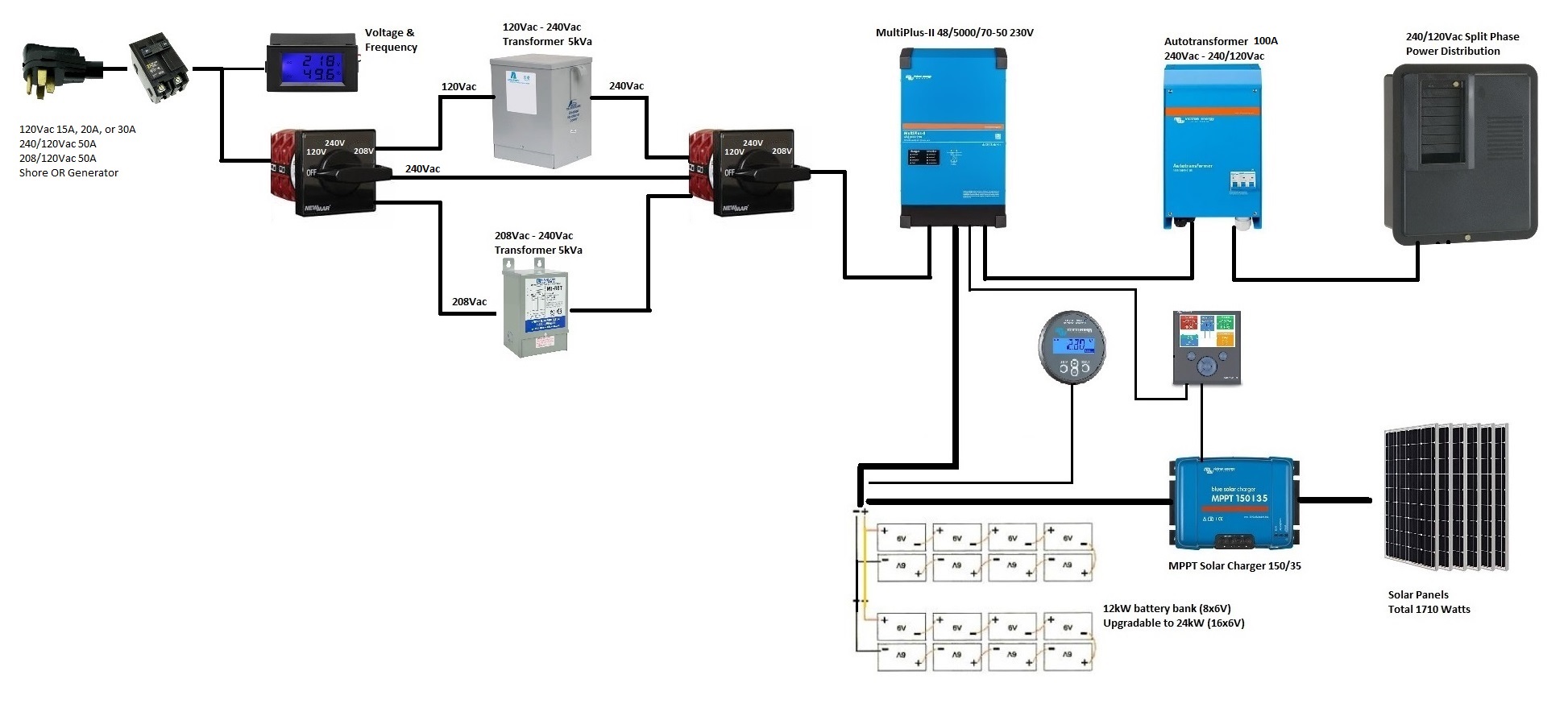
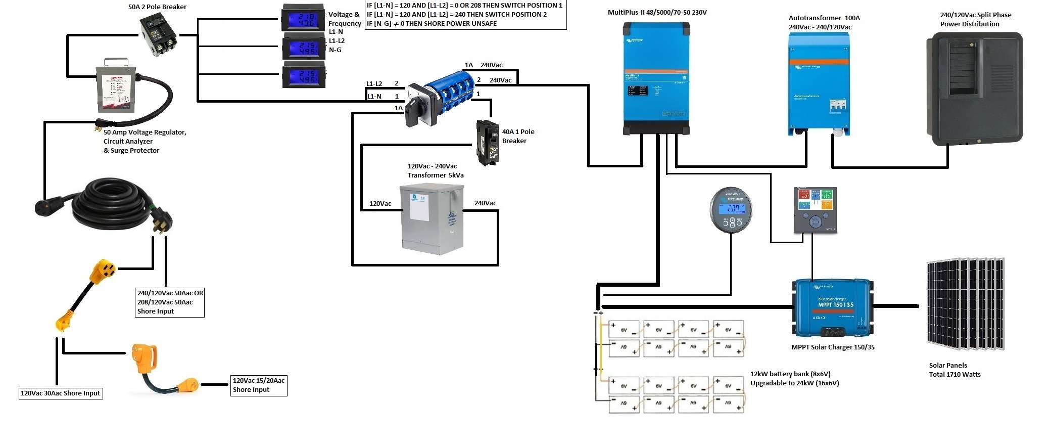
I know I am all over the place here with my evolving designs but I have yet another one now.

In general I like this design more, because it’s closer to normal and it lets you use the multiplus for all of its benefits.
I’m not quite sure why there are multiple switches upstream, but I’m sure you’ve either got that right already or you can easily get there.
Once you’ve committed to feeding the multiplus the “normal” way, you could consider skipping the 208-240 step up transformer entirely, if you feel that 120V 50A (really, 120V ~40A continuous) would meet your average needs and if your battery is large enough. You would just make sure your 120-240 step up is beefy enough to handle intermittent 6kVA and then let the inverter assist from the battery during times of peak demand.
You will only encounter 208V a handful of times a year on average, if you are moving a good bit. When you do, you will still have a 120V/50A you can take off the same supply with your new design.
Great point on using just one leg of the 208!
The 120-240 transformer is only rated to 5kva and a 7.5kva model is significantly larger, heavier, and more expensive but I would be fine with limiting and protecting it with a 40A breaker.
I used 2 upstream switches because I didnt like unnecessarily electrifying the transformers (from the secondary coils) when they are not in use. A side benefit of eliminating the 208 transformer is that I can use a readily available 2+off position 4 pole switch that effectively does the same thing as the two switches.
I am quite happy with this version. Thank you again for all your feedback.

Actually, the center tap should be at 0v. As long as it's floating or grounded you will have no issue. The center will be a created neutral. As referenced to either hot leg it will be 110v (since you mention 50hz I'm assuming 220v L-L). If by chance you run into a grid with a neutral (North America) that autotransformer will try to balance the two hot legs versus the neutral and there is the possibility of overloading it, especially if your circuit is shared by other users. (RV park or Marina is a common example)
1. The center tap will be at 120V with respect to either line. That means a set of feed wires running out of the transformer will be energized, at 120V.
2. He doesn’t mention 50Hz. And we are on a 60Hz system here.
3. Just for the OP’s reference, USA has been at 120V nominal for a long time. 110V is an anachronism.
4. When he is feeding 240V, he should have only three incoming conductors, including the safety ground.