question

svent avatar image
svent asked

Venus OS on Raspi - some questions

Hey there,
I installed the most recent Venuis OS on a Pi 3 B+ and did my first steps and now...have some questions ;-)

First the setup:

- 2 Solar Panels
- SmartSolar MPPT 100/30
- BMV 712
- LifePO4 battery with JK BMS
- Inverter to generate 240VAC
- Shelly Pro 1 PM at the output of the Inverter


NO mains as it is a stand-alone system in an allotment garden.

I installed the following from github to make the Shelly work:
https://github.com/Halmand/dbus-shelly-1pm-and-pm1-Plus-pvinverter-multi-instance

I also installed the GUI mods

Currently I draw about 1300W via the Inverter (charging my car).

In the Portal I see:

2023-08-19-13-11-48-window.png


The remote console shows:

2023-08-19-13-08-54-window.png


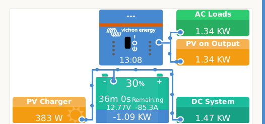
I setup the "Position" of the Shelly to "1", the shelly is setup as PV Inverter.
Before that it was not visible at all.

My questions:
How can I tell the system
- that there is no mains
- that it should not add the Power of the PV Charger and the Inverter

Is it that easy that I have to setup the Shelly as "Inverter" and not as "PV Inverter" ?


What I also wonder:
In the remote console it seems as if the DC System (Charger, battery, and DC system) is completely separated from the upper part.


Another issue:
The MPPT and BMV are connected via a genuine victron cable, the JK-BMS via a simple USB/TTL converter (non isolated).
I got disconnects of the BMV and MPPT that made a restart necessary to have them visible again.

Might that be caused by the missing isolation in the BMS connection ?


Any help is highly appreciated.

Thanks in advance

S.


Venus OSdc systempower
2 |3000

Up to 8 attachments (including images) can be used with a maximum of 190.8 MiB each and 286.6 MiB total.

4 Answers
bathnm avatar image
bathnm answered Ā·

@SvenT It sounds like you have no DC system, yet it looks like you have configured the VenusOS with Has DC System, or you have configured the BMV as a DC system monitor. This means that the system thinks you have DC consumables and has added it to the display.

The inverter knows how much AC output it is providing and so the Shelly is again a duplicate reading. As you have told it, it is on a PV inverter it is reporting it as that.

As you basically have a BMS Controlled Battery (JK-BMS); MPPT and Inverter I would only expect 3 components to be displayed. The AC output would come from the Inverter; Battery details from the BMS and solar from the MPPT. Therefore the Shelly and BMV are duplicate readings and not needed, try disconnecting them and see what you get!


2 |3000

Up to 8 attachments (including images) can be used with a maximum of 190.8 MiB each and 286.6 MiB total.

svent avatar image
svent answered Ā·

Hey there,
thanks for the reply.

Maybe I was somewhat unprecise so please allow to clarify with a few more details:

a) JK BMS:
Ccurrently the JK BMS is not connected. As described I have disconnects of the BMV and the MPPT and so I unplugged the JK BMS already.

b) Inverter
The Inverter is a very simple one (not from Victron) and so the Venuis does not get any data from the inverter - that was the reason why I connected the shelly.

The battery (in the GND line the Shunt of the BMV is placed) supplies the following components:
- the 12V side of the inverter
- some lights in the garden
- a water pump (12V)
- some control relays and circuits in the cabinet

So my assumption was, that I need to configure "DC system".
Was that wrong?

As you see in the portal screenshot, the line to the upper blue box is "Aus" (OFF).
So it seems as if the Venus does not recognize the Shelly as Inverter reading.
If I understand it correct, as it is a "PV Inverter" , Venus "thinks" that the energy comes from solar and not from 12V.
So from my perspective, the Shelly must be presented to the dbus as an Inverter right?

I think for that I have to change the Python code but there it should be possible right ?

Is that enough that the overall power calculation is correct?


In the upper shown diagram I would expect:
- about 400W from solar
- about 1100W from battery

These 1500W feed the inverter and draw the load of 1340W.
The difference between 1340 and 1500W is the power that goe sinto the DC System (to supply controller, relays, light, and also some watt are needed because the inverter has only 90-95% efficiency.


Thanks in advance.
S


2 |3000

Up to 8 attachments (including images) can be used with a maximum of 190.8 MiB each and 286.6 MiB total.

bathnm avatar image
bathnm answered Ā·

@SvenT You will have to modify things to get what you want. The system believes you have a PV Inverter as that is what gets displayed when you set the shelly to that mode. The system therefore thinks you are sending in 1.34Kw from the PV inverter and consuming it all through the AC loads as the system has no other information to know what is happening.

VenusOS is designed to work with Victron inverters and you will find lots of changes needed to trick it into thinking your inverter is a Victron one. It is not just the AC meter, but the whole of the VE.Bus communication and state tracking that the system will expect to get the inverter icon functioning correctly. If you work it out, do post for the benefits of others but not sure how much help you will get from the forum.

2 |3000

Up to 8 attachments (including images) can be used with a maximum of 190.8 MiB each and 286.6 MiB total.

olafd avatar image
olafd answered Ā·

Hello @SvenT,

@mr-manuel has developed this service venus-os_dbus-multiplus-emulator and @pulquero has developed the DCSystemAggregator service.

Hope these services may help to get your system working.

2 |3000

Up to 8 attachments (including images) can be used with a maximum of 190.8 MiB each and 286.6 MiB total.

Related Resources

Victron Venus OS Open Source intro page

Venus OS GitHub (please do not post to this)

Additional resources still need to be added for this topic