I'm installing a BMV-712 in my RV. I have two 12v batteries connected in parallel. I was going to connect both battery negative wires to the "Battery" post on the Victron shunt. But, the quick start guide shows the negative wires from each battery going to opposite sides of the shunt. The quick start guide referred to the second battery as a starter or auxiliary battery. In my case, it's neither of these. My question is do I connect both negative battery cables to the "battery" side of the shunt or one on each side of the shunt?
asked
Need help connecting negative battery cables to BMV-712 shunt with two 12v RV batteries in parallel.
Both neg wire to the battery side of the shunt is correct all other Neg wires NO matter what to the load side of the shunt.
If you need any further help please post a diagram of the setup
Thanks
I am considering a similar set up with two 100Ah batteries in parallel. Do I set the battery parameters as 100Ah or 200Ah because each one is 100Ah.
Thanks JohnC, that was what I was thinking. I also noticed on the manufacturers website for my battery it says it is an 81Ah. I was told by the RV dealer it was a 100Ah battery. I wonder if it is customary to round up.
Nope - A few Ah is OK, but rounding up by 25% would not be on...
Note that the same battery will have a different Ah rating at different discharge rates - higher at a slower discharge rate.
Sometimes batteries are marketed with the 100h discharge rate, but the 20h discharge rate is what should be entered into the BMV (and it will adjust capacity according to the actual discharge).
However, I still don't think that would explain this large magnitude of difference.
I would go back and ask/challenge the dealer that sold you the battery, ~25% less capacity that what you thought you had is a big deal in my opinion.
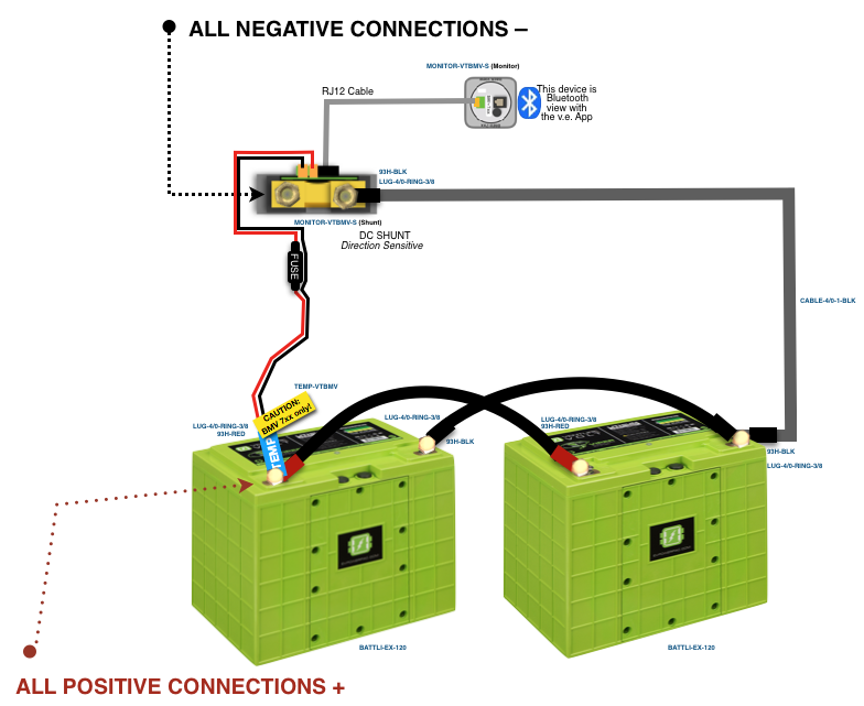
@Paul B I have the same question as OP but I am a little confused about both Neg wires going to to shunt as in your reply. Here is a diagram from AM solar. Batteries are wired in Parallel and shows only one Negative cable to battery side of shunt. IS the better option to run two Negative to shunt or wire as in diagram?
Thanks.

The diagram is the correct way. In the case there battery balance is being considered too. And both -ve's make it to the shunt.
Hi, I have almost identical setup but I have the 2nd positive supply cable (+B2) going to the + terminal on the battery on the right.
Is this ok or should I use only 1 (+B1) when running in parallel like the above diagram ?
Also, is there a way for the BMV-712 to be able to read individual voltage/capacity of both batteries individually when setup in parallel like @RFT's AM solar diagram above ?
And is there any difference or benefit of having both neg run straight to the shunt as opposed to having the jumper between batteries and single neg cable to the shunt like the AM solar diagram ??
Thanks
Gav
By 2nd Positive Supply cable - do you mean the ones that were supplied with the Shunt?
The First Positive lead that goes to the Shunt is actually for Powering the Shunt as well as being able to measure the voltage across the terminals. The 2nd (Aux/B2) should not go to the other battery if you have it in Parallel. It can be used for Monitoring a Starter batter, or if you had the Batteries in Series it is used for Measuring the Mid-point - which is then a way for you to know your Series batteries are Healthy, i.e. one battery is not lower in charge than the other, which might indicate dead cells.
Your 2nd and 4th Paragraph have this as the answer:
The Diagram illustrates the ideal battery setup where you are not using Bus Bars. This is because the Parallel Path for Current is identical across Both batteries, i.e. it is as far to travel through B1 as it is to travel through B2. Therefore current will split across both evenly.
The other way to achieve this is the use of Bus Bars - where you tie the Positive lines of each battery to the Bus Bar, and Negative of both batteries to another Bus Bar - then any Outbound/Inbound lines from the Bus bar(s) will evenly distribute to Both batteries.
The 3rd alternative - is Precisely SAME LENGTH cables directly connected to the Shunt to Both Negative terminals, and the same for your Positive terminals to wherever they need to go. This is not really an advised setup, as it can become bulky on the Shunt, and make cable management harder.
You will never be able to read the individual voltages Per Battery when setup in Parallel.
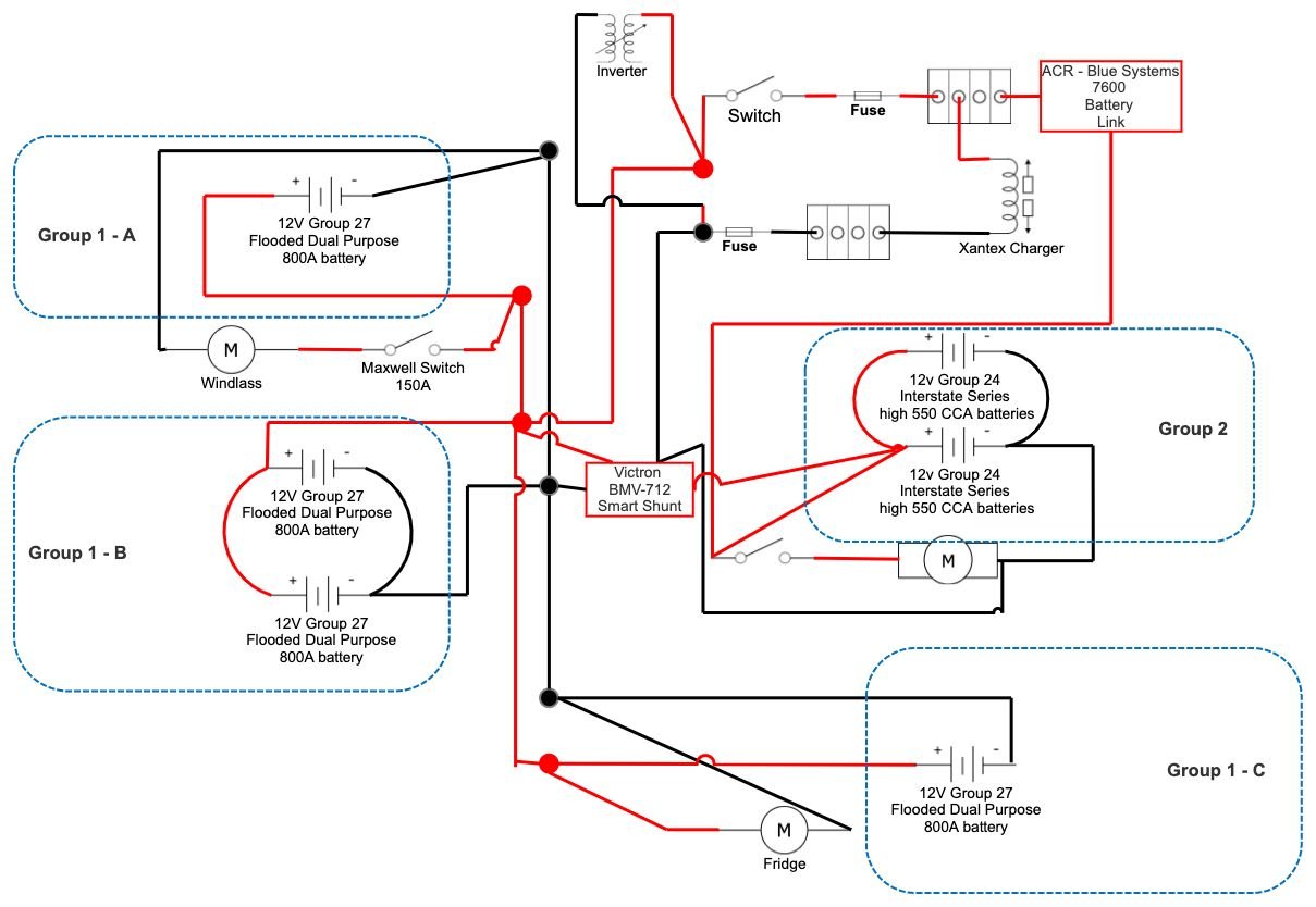
Hi there, wondering how I do this. Below is my setup as it stands. Having a hard time figuring out where I'd place the shunt. My Group 1 is basically all over the place. Where would I place the shunt to monitor that group? (the black and red big dots are basically busses)
Shunts always go as the Very last thing before the Negative terminal of a Battery or Battery group, and from there it is in between the Battery(group) and anything which that source powers. The idea is it measures the current going through it, so anywhere else and it won't accurately measure. It also requires a Positive power source to run, and that same Positive source needs to also be on a Common bus to your Negative. It is common enough to just make sure it is connected to the Positive bus of the same Battery(group.)
The Problem you appear to have is Multiple Battery sets within your group, where you have created a common ground. However that Common ground is also used by Group 2.
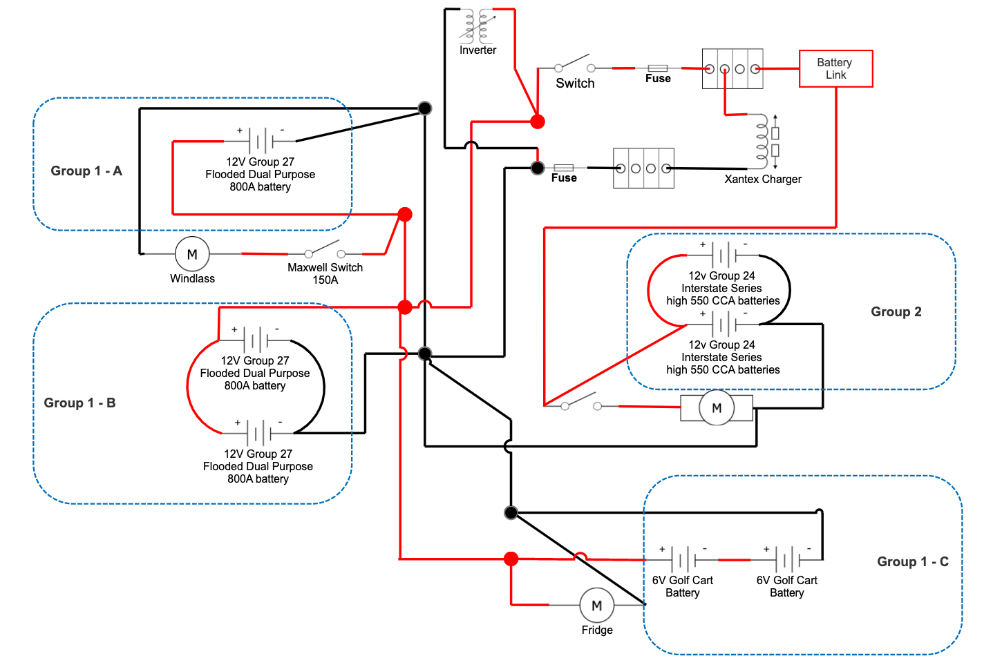
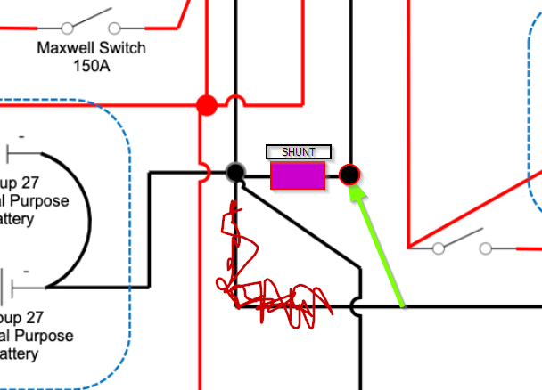
What you need to do is put the Shunt in between Group 1 and Group 2 then Bus bar from there to the rest of your Common ground circuit - so in below adjusted image, the Line from Group 2 is cut to the Common Bus Bar, Shunt goes in, and Group 2 Negative goes to the Load side of the Shunt, but the Battery side.

This will mean Group 2 is Unmeasured, but still free to travel to the rest of the circuit, and Everything from Group 1 will have to travel through the Shunt to get to the rest of the circuit.
You obviously have a signficiante amount of Battery power of course, so make sure you size your Shunt accordingly.
Thanks so much. I suspected it would be somewhere around these lines. This helps a lot though since I was not sure what to do with the negative for group 2.
That said, no clue if the 712 Monitor comes with a shunt and which it might be. But I just ordered one. From the packaging seems it comes with one. I don't know what shunt I should get but from what I gather from the fusing on the system it should be anything that handles 40A...?
If you allow me, one more question. To monitor bank 2 with the 712, do I just need to get an extra shunt and put it between that bank's negative and the rest?
Thanks so much!
Not an answer just a question...Is group 27 really an 800A battery? Do you mean cranking amps and not AH correct
?