question

Darlene avatar image
Darlene asked

Fronius Primo cooking micro-grid batteries

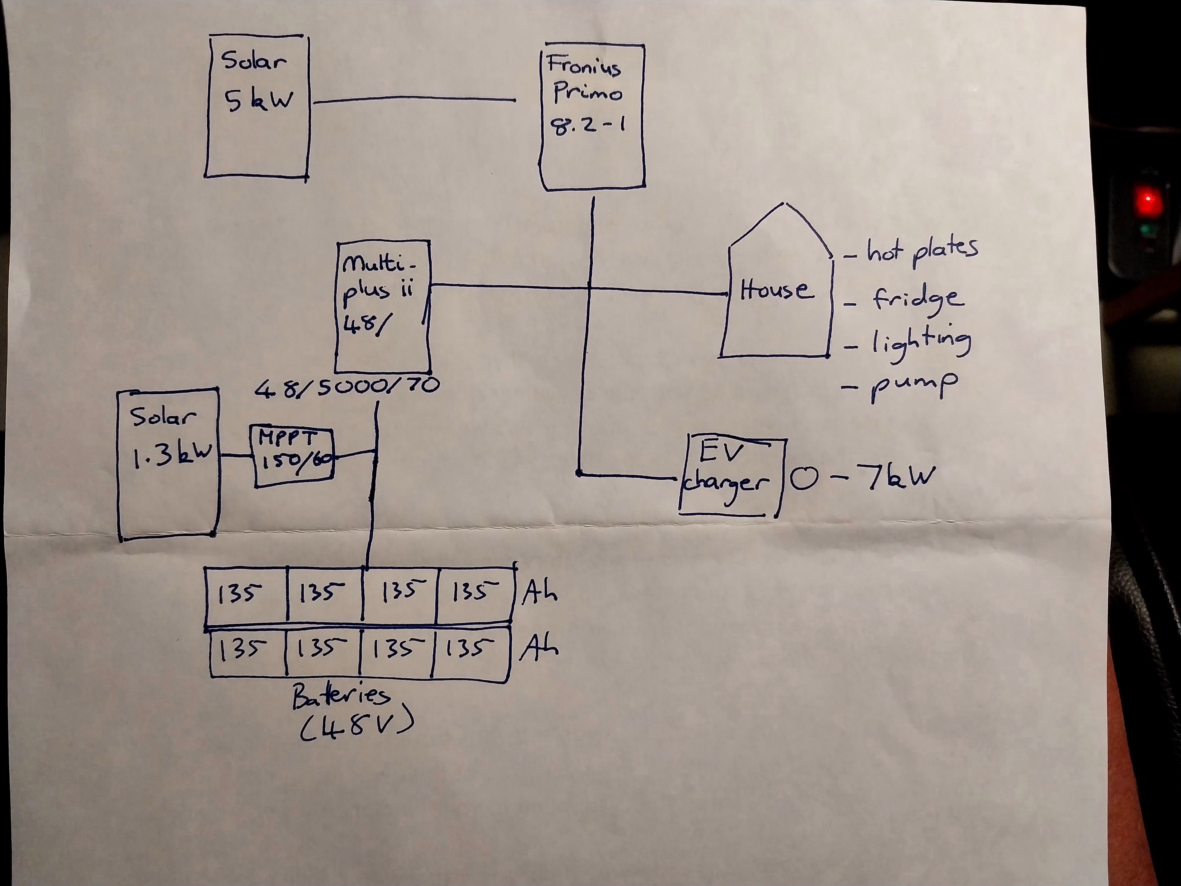
We have a Fronius Primo 8.2 fed by approx 5kw of solar, coupled to a microgrid consisting of a 5kva Multiplus II, 1.3kw solar panels and eight 135Ah 12v AGM batteries. The Primo is set to MG50 and the Multiplus has been configured as a microgrid. We used this set up to successfully charge our EV for the first time two days ago. Everything worked, with the Primo generating 4-4.5kw most of the time, and the smaller solar system that feeds the battery bank via an MPPT picking up the slack to supply most of what the charger needed. The car wound down charging gradually, and presumably as whatever slight deficit there was in the battery bank was topped up, the Primo gracefully throttled itself, with the lights on the Multiplus changing from bulk, to absorption, to float, and the display on the Primo showing 0w in the absence of all loads. What more could we want? The following day we wanted to use our set up to run a 1.5kw transfer pump for an extended period. When we switched the Primo on the batteries were already full, but the Primo began hammering them with around 1800w, and the Multiplus showed bulk charging. The batteries began making a bubbling, sizzling sound – not good at all! Why didn’t the Multiplus tell the Primo via frequency shifting that it didn’t need to be pumping juice into the batteries? We had made two small changes via VEconfigure after our successful EV charging session, but can’t see how they relate to this sudden departure from proper functioning. 1. We raised the battery voltage at which the Multiplus shuts down and re-starts after a shutdown, to offer the batteries better protection. 2. The battery type was unspecified, so we changed that to AGM/Gel. After the Primo decided to boil the batteries we made one further change, altering the rate at which the Primo can charge the batteries from 70amps down to 10amps. This made no difference to its desire to overcharge the batteries, but at least the reading it gave was a bit lower, at around 800w. We weren’t able to use the Primo for the pump today, and had to rely on the smaller solar system attached to the Multiplus instead. We are stumped. Can anyone please shed some light?

One further question, if I may: Is there any other reason for the 1.0 rule than to protect against voltage spikes in the event a load that has been consuming the PV yield is suddenly removed and the Multiplus is not rated to accept that yield? If such sudden events could be managed to give the Multiplus time to respond, would it be viable to have, say, an 8kw solar array behind the Primo?

All help much appreciated.

battery charging
1 comment
2 |3000

Up to 8 attachments (including images) can be used with a maximum of 190.8 MiB each and 286.6 MiB total.

Alexandra avatar image Alexandra ♦ commented ·
@Darlene

When switching the battery type to agm/gel did you check the voltages were then correct?

Did you also restart the gx at all. Are all comms working ok?

0 Likes 0 ·
4 Answers
Darlene avatar image
Darlene answered ·

As far as gx goes, we don't have one. Is it absolutely necessary? As far as I can see the Primo doesn't have a datamanager (probably for supply chain reasons :-( ).

I'm not well versed in these matters, so I don't know what "comms" are.

Regarding voltages....the only tab I recall with voltages was the one requiring a DC input low shut-down, DC input low restart, and DC input low pre-alarm, which we raised significantly to make sure the EV charger can't overwhelm the battery bank if weather conditions reduce PV yield and also yield of the small solar array hooked up to the Multiplus. Could these changes have affected the Primo's behaviour. Or are you referring to another tab concerning voltages that I don't remember.

Our set up is at a remote location, and I'm not there atm, so I can't tap into it and pull up data.

1 comment
2 |3000

Up to 8 attachments (including images) can be used with a maximum of 190.8 MiB each and 286.6 MiB total.

Alexandra avatar image Alexandra ♦ commented ·

@Darlene

A GX is necessary for the victron to be able to control the Fronius. Especially since it is AC coupled.


https://www.victronenergy.com/live/ac_coupling:fronius

0 Likes 0 ·
Darlene avatar image
Darlene answered ·

Our understanding is that the basic communication between the Victron Multiplus and the Fronius Primo takes place via the AC connection through frequency shifting and this should be enough for the Victron Multiplus to tell the Fronius Primo it needs to reduce it's power output when the batteries are reaching their fully charged status. This control mechanism didn't seem to work when we started with fully charged batteries and started up the Fronius Primo as well so we could use its power output to run a 1.5 kW pump. It looked like the Fronius Primo was providing surplus power that went towards charging the batteries even further, but this wasn't required because they were still fully charged. We're really wondering why the Victron Multiplus frequency shifting didn't seem to work in this case and the Fronius Primo kept supplying power to charge the batteries while it wasn't needed and even worse it led to the batteries starting to make bubbling, sizzling sounds.

What additional control options would the GX Cerbo provide us with compared to the already active frequency shifting? Could you provide us with the menu options we should look into or use? Our system is setup as a basic MG50 system with additional battery charging provided through a 1.2 kW solar system and a Victron MPPT 150/60.

3 comments
2 |3000

Up to 8 attachments (including images) can be used with a maximum of 190.8 MiB each and 286.6 MiB total.

Alexandra avatar image Alexandra ♦ commented ·

@Darlene

If you dont want the fronius to feedback to the victron, you will need to add the fronius meter in and have it to not feedback to 'grid' (in this case the Victron) using the meter.

With no comms between anything other than frequency shifting you are going to have alot of issues.

Or you can set the multiplus to have zero amps on the charger tab so it does not charge from 'grid'. Or disable the internal charger entirely. I have not tried this option as usually there is a GX in the systems we install.

1 Like 1 ·
Darlene avatar image Darlene Alexandra ♦ commented ·
We changed charging current settings on the multiplus via VEconfigure, down from default 70amps to 10amps, but it didn't appear to help. Is this because that setting relates to current coming from AC in rather than AC out?
0 Likes 0 ·
Darlene avatar image Darlene Alexandra ♦ commented ·

One more thing: I read that "In ESS systems and systems with managed battery (see the Battery Compatibility manual), the internal charge algorithm is deactivated". We are using PV inverter Support Assistant. Would that also deactivate the internal charge algorithm?

0 Likes 0 ·
daza avatar image
daza answered ·

Can we see the schematics of your sight to get better detail?

3 comments
2 |3000

Up to 8 attachments (including images) can be used with a maximum of 190.8 MiB each and 286.6 MiB total.

daza avatar image daza commented ·

Is the fronius on the out put side of the inverte? As far as I understand it has to be a grid down situation I could be wrong with that one but to change frequency it would have to happen from the inverter output so fronious would connect soully to the inverter output in order for frequency shift otherwise you’ll have grid frequency being pumped in and the inverter shifting frequency I would image your system would do lots of strange things. Please confirm what outputs of the Victron are used and what connects to what as the diagram just shows it all connected as one. PS the inverter should be bigger than the solar array that is feeding into to it, that’s what a distro told me when I was looking at what inverter to go for.

1 Like 1 ·
Darlene avatar image Darlene daza commented ·
My drawing is not great. The pv inverter is connected to AC output 1. There's nothing attached to AC input, because it's an off-grid set-up.


Ideally we would be using a bigger Multiplus, but I have read that 5kva can deal with 5kw in set-up like this. We don't take a set-and-forget approach when using the Fronius, and instead try to make sure the EV charger is consuming all of the yield the Fronius is delivering plus a little from the Multiplus+Batteries+1.3kw Solar array. Once things are running the Fronius reins itself in when the car charger slows down and finally stops. The problem is with starting the Fronius when the batteries are full and there is no load yet. We have worked out we need to create load on the system first. We plan to increase the battery bank to be able to start the car charger at a low setting, then switch on the Fronius, then dial up the car charger.

0 Likes 0 ·
Darlene avatar image Darlene commented ·

Below is a homespun drawing...hopefully it's legible.


20230325-225833.jpg


We are aware that our battery bank is significantly smaller than recommended, but we only use the PV inverter to charge the car, and carefully monitor what is going on, to avoid excesses to and from the batteries.

Today we arrived at the conclusion that we can only start the Fronius up if we have depleted the batteries a little. If they are full, it's a fiasco, with a Fronius error message saying the microgrid frequency is too high, and shutdowns caused by either the Fronius or the car charger. Given the complexity of the various devices in this set-up the solution is extremely pedestrian and primitive by comparison: apply a load to the batteries before switching the Fronius on. Once it is up and running it works as we understand it should, and cuts back its output as the car winds up charging, so that the batteries are not overloaded.


0 Likes 0 ·
scraggs avatar image
scraggs answered ·

Without a Cerbo you won't be able to set a DVCC maximum charge current, so it could be fun setting up the charge current for the Multi and MPPT to get the best from your system without putting too many or too few amps in with that size battery pack.

1 comment
2 |3000

Up to 8 attachments (including images) can be used with a maximum of 190.8 MiB each and 286.6 MiB total.

Darlene avatar image Darlene commented ·

Already put the question to Alexandra, but 2 heads are better than 1, so:

We reduced the charge current of the Multiplus using VEconfigure, from default 70amps down to 10amps, but it didn't prevent the sizzling noise from starting in the batteries again, so it looks like the Fronius was still pumping in all it could. My question is, does that charge setting only relate to AC in, not AC out? It looks like it, from a diagram I've since seen. I was wondering why I would need an extra device to regulate DVCC when I can adjust setting on the Multiplus via VEconfigure, but if AC out current is not affected by such setting changes I can see why.

I also saw this: "In ESS systems and systems with managed battery (see the Battery Compatibility manual), the internal charge algorithm is deactivated". We are using PV inverter Support Assistant. Would that also deactivate the internal charge algorithm?

The size of the system has become an issue since adding AC coupling; we're going to beef it up.

As long as we 1) create a load before switching on the Fronius, and 2) set the EV charger to use all the Fronius delivers plus a small amount from the Multi+Batteries+1.3kw Solar array everything works elegantly.

0 Likes 0 ·