question

calle avatar image
calle asked

Battery connection MPPT RS 450/200

834beca7-528b-41ac-af6c-3d0c0af6594d.jpega8190ba6-995e-4429-9206-4705fcf7f6d9.jpegHello!


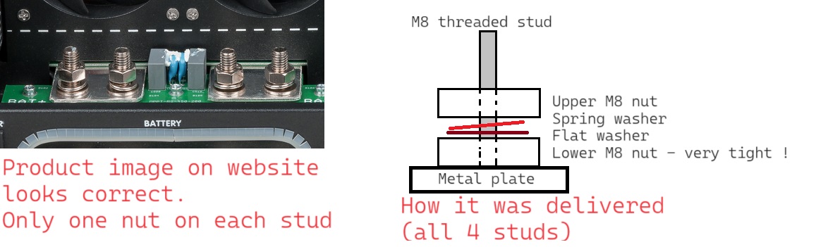
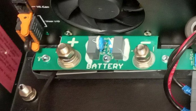
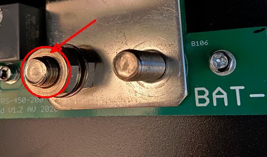
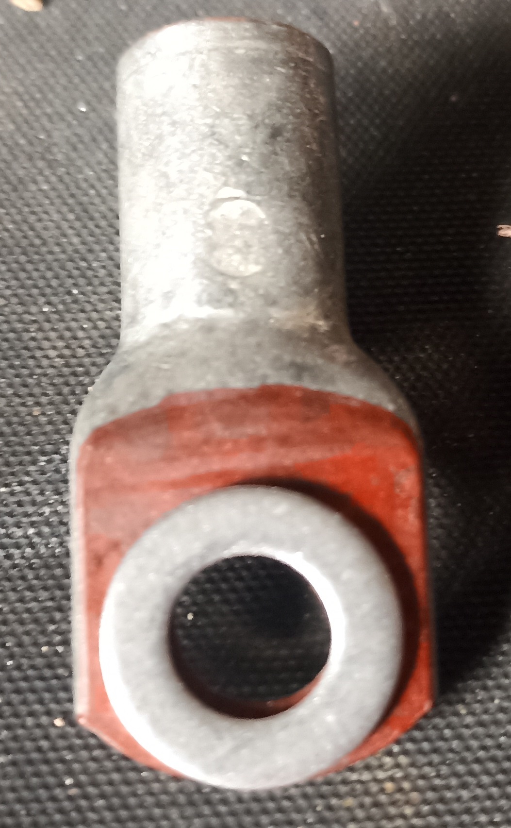
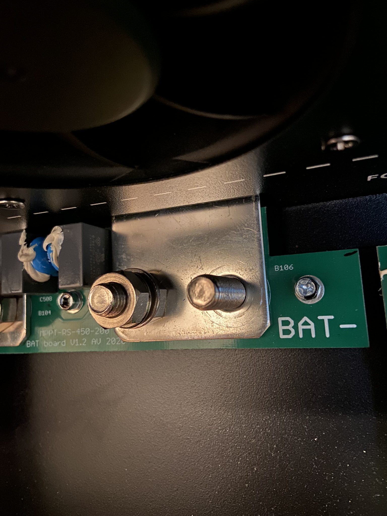
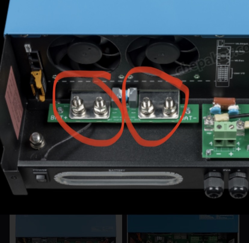
I can’t find instructions on the connection for battery/48V. The torque is specified to 14 Nm, but am I supposed to remove both nuts (as delivered the terminal bolt has nut-washer-spring washer-nut)?


Is the cable shoe supposed to be connected on top of the first nut or directly on the terminal with two nuts?


mppt rsbattery connection
2 |3000

Up to 8 attachments (including images) can be used with a maximum of 190.8 MiB each and 286.6 MiB total.

11 Answers
wkirby avatar image
wkirby answered ·

Remove the nut and the washers from the stud. Place the terminal on first, then the plain washer, then the spring washer and finally the nut.
Use one stud or two depending upon your wiring configuration.

1675589335852.pngConsult the wiring unlimited book for detailed information about wiring:
https://www.victronenergy.com/upload/documents/Wiring-Unlimited-EN.pdf


1675589335852.png (225.7 KiB)
4 comments
2 |3000

Up to 8 attachments (including images) can be used with a maximum of 190.8 MiB each and 286.6 MiB total.

calle avatar image calle commented ·

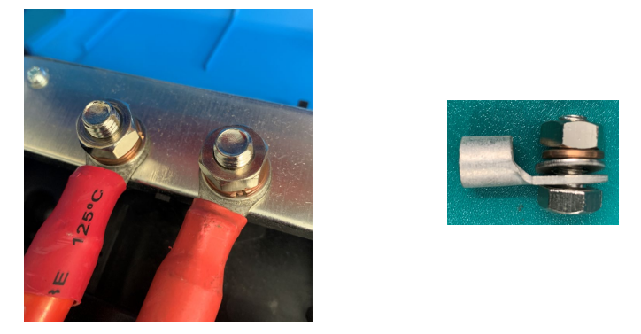
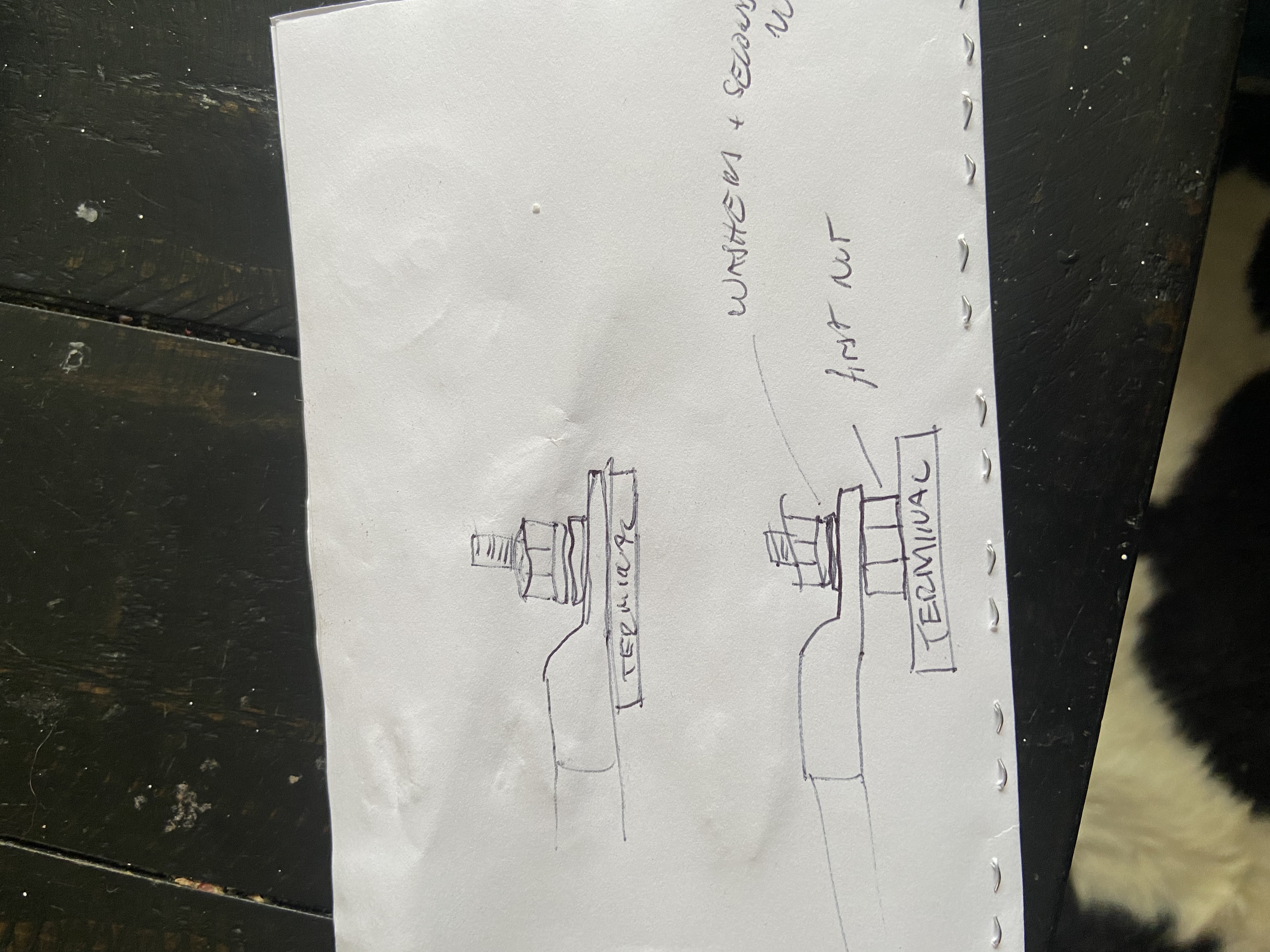
I’ll make a simple drawing!


0 Likes 0 ·
wkirby avatar image wkirby ♦♦ calle commented ·
There should never be anything in between the cable lug terminal and the flat metal terminal or busbar. Indeed, the two should be in direct contact.

The torque specifications (14nM) are to ensure that the bolt is not over tightened.

0 Likes 0 ·
calle avatar image calle wkirby ♦♦ commented ·
Thank you! My suspicion was correct. Is there some other reason the RS is supplied with two nuts on each bolt? I’ve put two nuts on the bolt in high vibration environments, so that one locks against the other, but I can’t find any information about it in this case.
0 Likes 0 ·
calle avatar image calle commented ·

Excellent article, thank you! I’m still however unsure about the RS. The logical thing would be to connect the cable shoe first, directly against the “big” terminal for minimal resistance. It makes me unsure though when it has two nuts on one terminal bolt, it made me consider if it has something to do with the physical tightening of the terminal, if the bolt is too weak to directly handle 14Nm against the terminal? If one nut is used to make it stable enough against the terminal.


I can get better pictures tomorrow when I’m on site again.

-1 Like -1 ·
mbruehl avatar image
mbruehl answered ·

Hey, thanks for the question and clearing that up - I had the same thing in my mind "Is this for torque stability? Do I ruin the connector, if I remove both nuts and tighten?"

2 |3000

Up to 8 attachments (including images) can be used with a maximum of 190.8 MiB each and 286.6 MiB total.

gerhardlang avatar image
gerhardlang answered ·

Finally I had the same problem.

The second nut seemed to be absolutely fixed (surely more than 14 nm) that I thought to break something when removing.

I removed it - nothing broke - and it definitely makes more sense for 200A to have the cable directly on the terminal.

Frankly spoken, I to not understand why Victron does confuse customers by this unnecessary second nut.

3 comments
2 |3000

Up to 8 attachments (including images) can be used with a maximum of 190.8 MiB each and 286.6 MiB total.

nesswill avatar image nesswill commented ·

Frankly spoken, I to not understand why Victron does confuse customers by this unnecessary second nut.

The second nut (jam nuts a smaller nut if no washers are used) might be used to lock the first nut to stop it coming loose under vibration. Standard practice going back over 100 years.

0 Likes 0 ·
edstobi avatar image edstobi nesswill commented ·

This is the first Victron device that is countered with a 2nd nut. Then please also include this into the documentation!

I hope that we don't come up with such vibrations that this becomes absolutely necessary for a second counter nut, because then I have to fasten the device in a completely different way to my wall and also secure the rest of my screws against vibrating loose.
Standard practice going back over 100 years, yes BUT:
we are developing further and in the meantime we have other possibilities to protect ourselves against such processes. The first way was the spring washer where its ineffectiveness was recognized in 2003 and was taken out of the DIN 127 A und B

Today, we use an expansion screw, a screw of a higher strength class that is noticeably elastically expandable. Thanks to its slender and particularly long shaft, it behaves like a pre-tensioned tension spring in a bolted joint.


I still have one. Take a look at the internet and see what torque you should use to tighten M8 bolts. M8 starts at 15.3 Nm and goes up to 20.4 Nm depending on the material.

I find the values specified by Victron to be very low in order to create a gas-tight transition over a wide area, especially if the ring cable lug is not 100% flat, which is usually due to the production process.

0 Likes 0 ·
lilikoi-heavy-industries avatar image lilikoi-heavy-industries edstobi commented ·

They aren't stainless bolts, they're a brass alloy I believe. They look silver because they're tinned. That's why the torque spec is so low on lugs like this typically.

0 Likes 0 ·
honu avatar image
honu answered ·

So victron...what is the answer..?

2 |3000

Up to 8 attachments (including images) can be used with a maximum of 190.8 MiB each and 286.6 MiB total.

mondeoman avatar image
mondeoman answered ·

I have the same question, why are there TWO nuts on each stud with a flat washer and spring washer between the nuts? That is how my MPPT RS 200 was delivered from the factory.

The bottom nut seems really, really tight, I'm afraid of breaking something if I try to remove it.

But if I keep it, then the lug would have to be connected between two nuts, with small contact area and the current would flow through the stud and the nut. That doesn't seem right!mppt-rs-nuts.jpg


mppt-rs-nuts.jpg (100.1 KiB)
2 |3000

Up to 8 attachments (including images) can be used with a maximum of 190.8 MiB each and 286.6 MiB total.

Alex Pescaru avatar image
Alex Pescaru answered ·

You all worry too much...

Take a look at any 200A fuse, it's cross section wire and the length of that wire.

That surface between the nuts and washers, for the "distance" the current has to travel on that section, is more than enough...

As a comparison, take out the main cover and look at the DC H-bridge and it's FET transistors. Look at how small in section are the terminals of those transistors. No more of 10mm^2 the sum of all pins in section and the whole current on full load must pass through there.

And you worry about 35mm^2 (or more) wire section and the nut/washer section...

All is down to the length of the wire with a certain section.

And in between the nuts there is almost no distance... Pardon the pun... :-))))

But that is only my opinion and it may be far removed from the truth...

Alex


2 |3000

Up to 8 attachments (including images) can be used with a maximum of 190.8 MiB each and 286.6 MiB total.

delf67 avatar image
delf67 answered ·

Questions like this on the forum do concern me a little, as they indicate that there are many untrained people out there installing this equipment, and while they may be more than capable of following instructions, they do not necessarily understand the principles behind those instructions. In this case the principle that you want to maximise the contact area between the lug and the terminal, and putting anything (nut, washer, peice of heatshrink on a badly made up lug etc) between them will seriously reduce that contact area, resulting in heat being generated. Electrical fires kill people around the world every day and there is a reason most countries require some sort of qualification to work on electrical systems.

2 |3000

Up to 8 attachments (including images) can be used with a maximum of 190.8 MiB each and 286.6 MiB total.

Alex Pescaru avatar image
Alex Pescaru answered ·

In addition to what I've said above, here's, below, the battery connection of an Multi RS.

Even it's designed for 100Amps, try to connect the wire lug terminal, without the nut, directly on the PCB... I think not...

It's now even designed with a proper wide, rectangular pad for the wire lug terminal, not to mention the PCB material is not designed for such direct connections.

So in this case, lower nut is a must, so the lug terminal will be connected between two nuts and washers for sure. And it's OK, because of what I've said above, in the previous post.


pcb-conn.jpg


pcb-conn.jpg (104.3 KiB)
1 comment
2 |3000

Up to 8 attachments (including images) can be used with a maximum of 190.8 MiB each and 286.6 MiB total.

delf67 avatar image delf67 commented ·

burnt-13a-socket.jpg

13A socket.....

Personally, I'd be taking a bit more care on something designed for 100s of amps.

0 Likes 0 ·
Alex Pescaru avatar image
Alex Pescaru answered ·

And if we keep posting pictures about it, lets get into the math zone.

Below a nut with a contact area highlighted in red.

For an M8 nut, that red circle diameter is at least 8mm. The math tells us that the length of that circle, for a diameter of 8mm, is more than 25mm. With the width of the contact flat zone (red circle) of about 1.5mm or more, it will mean an area of more than 40mm2.

I believe it's more than OK for that connection.

screw.jpg


screw.jpg (41.2 KiB)
2 comments
2 |3000

Up to 8 attachments (including images) can be used with a maximum of 190.8 MiB each and 286.6 MiB total.

mondeoman avatar image mondeoman commented ·
Depends on the material of the nut.

Steel and stainless steel is not a very good conductor. Nickel plating might help.


0 Likes 0 ·
Alex Pescaru avatar image Alex Pescaru mondeoman commented ·


Use silver nuts and bolts... :-)))


0 Likes 0 ·
mondeoman avatar image
mondeoman answered ·

So I removed the lower nut and installed the lugs directly on the metal plate (busbar).
I think I now understand what is happening and why they added the second nut on the threaded stud.

With the lug directly on the busbar, the lower part of the cable rubs agains the lower part of the opening where the cables exit from below. The busbar sits too low or the hole to pass the cables is not aligned properly.

So they added a second nut to raise the lug such that the cable passes freely through the center of the cable opening.

I left the lugs connected directly to the busbar (i.e. just a single nut on the stud). This is a fixed installation in a building, I'm not expecting vibrations or anything that would cause the cable to rub against the opening.

2 |3000

Up to 8 attachments (including images) can be used with a maximum of 190.8 MiB each and 286.6 MiB total.

delf67 avatar image
delf67 answered ·

50mmxm8.jpg

Flat area of 50mm xM8 lug coloured red vs M8 washer.

Just saying, I wouldn't put a washer between this lug and the terminal.


50mmxm8.jpg (393.5 KiB)
2 |3000

Up to 8 attachments (including images) can be used with a maximum of 190.8 MiB each and 286.6 MiB total.

Related Resources