I’m planning the following setup. 4 x 380w panel in series of 2 connected to 2 different mppt 100/20. The output of each charge controller will end up on two different common bus bars, one for positive and one for negative. From here I would like to connect battery and inverter on the same bus bars. I need 2 charge controller because panels will be orientated in different directions to have a constant solar input. My question is: is there any danger of reverse current if one charge controller is giving max output eg. 20A and one is shaded, giving zero? If not, any problem if for some reason BMS cuts the battery and one of the charge controller is providing current and one other not? Also, I’m planning to charge the battery from this same common bus bars from AC via the inverter. Is there any danger of reverse current into the charge controllers if I start charging with the inverter via the bus bars to the battery, when charge controllers have no tension or current from the pv? Hopefully I explained myself, thanks in advance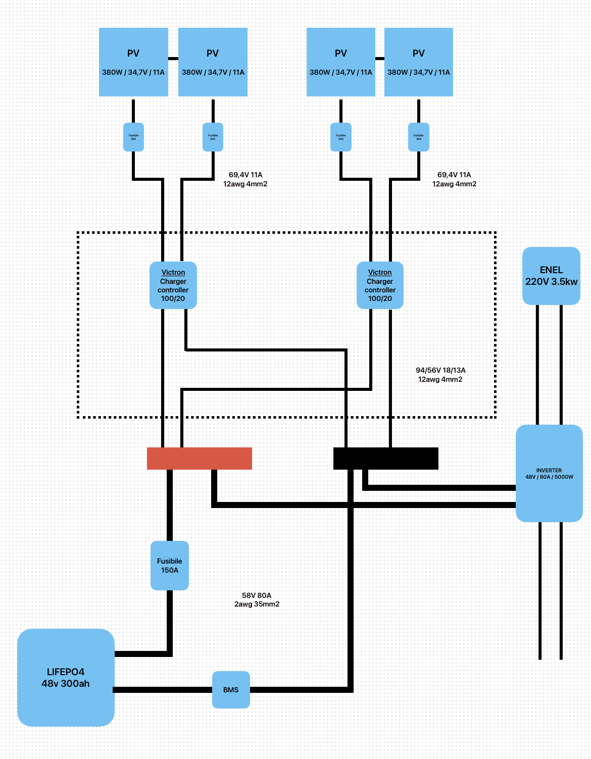
asked
Reverse current on common bus bars
Am I missing something? My question would be if your controllers are rated high enough? I would think you are limiting your potential output of your panels. Depending on your run from your panels to the controllers why wouldn't you go with 10 gauge wiring? I am using one 327w panel but twice the voltage. Using a victron 100/30 and I am seeing 21 amps. I realize the higher voltage makes a difference but I would be concerned if I was pushing the limits.
I think so. Not sure where you're getting 21A.
760W per MPPT
48V battery
760W/48V = 16A - a 100/20 is more than enough to handle each array.
Most charging will occur at an average of 54.4V, so 760W/54.4V = 14A.
A few comments on your diagram:
- Fuses exist to protect wires. The panels are self fusing and by definition will protect the wires. Fuses are not needed in a single series string. If you feel you must, you only need a fuse on one wire. A breaker that doubles as an on/off switch is preferred to a fuse.
- You need 25A fuse/breaker on the (+) wire between each MPPT and the bus bar.
- Make sure your 150A fuse is Class T.
No.
The chargers only accept as much current as they need to power themselves. Doesn't matter if one is putting out 100A and the other is zero.
It seems your concern is on the PV side. Even this isn't an issue.
Light gives voltage.
Intensity of light gives amps.
Current only flow from high to low voltage.
The "weak" panels will still have a Voc higher than the producing panels' Vmp.
You could technically put your two strings in parallel on the same controller and see basically the same output. it will be a little better with two.
Thanks for reply. Actually my concerns are not from the pv side, but from the bus bars side. (Red and black of the picture) On the pv side 2 panels are connected in series and than to the charge controller. Each charge controller output goes to the bus bars. Each output positive to the positive bar and each negative output to the negative bar. Now, let’s say 2 panels are shaded and 2 are in direct sun, one charge controller is producing zero and the output is zero, one is sending 20amps to the common bus bars where also the other charge controller is connected. Is there a risk some of this current flows into the silent charge controller? Probably not as the shaded one still have some voltage even with no direct sun. Other example, and probably more concerning to me.. during night, zero volts from the panels, both charge controller sending zero amps at the bars. If I start charging the battery from the inverter, via the common bus bars where also the charge controllers are connected, is there any risk some current flows into those damaging something?
Again, no.
Per above: "The chargers only accept as much current as they need to power themselves. Doesn't matter if one is putting out 100A and the other is zero."
Why aren't you worried about the battery pushing current into the 0A charge controllers? Battery is at 48V+, but they're not getting killed by the battery. The battery can deliver 100s of amps, but it only does so if there's a voltage difference, or a load that pulls that kind of current. Answer: You shouldn't be.
Chargers are sources when active. They are loads when inactive. You don't worry about plugging an 8W bulb into a socket that can deliver 1000W+ because it only pulls what it needs.
VOLTS are what causes current to flow. Amps are the flow created by a difference in voltage and the circuit resistance. The MPPT will simply sit there drawing a few mA to power themselves while the battery operates in its voltage range. It doesn't matter if you have 1A or 10,000A charging the battery with many different chargers.
If a source were to charge your battery to much higher voltages than the MPPT (and the battery for that matter) are designed to handle, then yeah. You can damage your MPPT. However, you'll have a destroyed battery and an unregulated runaway charge source. Two popped MPPT won't be on your radar compared to the catastrophe in progress.
All clear, thanks again. I wasn’t worried till I read something this evening about reverse current, and someone in the past using some sort of protection breaker to avoid reverse current from the battery to the charge controller and pv. Now this kind of protection is integrated in the charger controller I guess, I was wondering if there was any limitation, but it’s probably just me wanting to be extra safe.