question

mysik avatar image
mysik asked

MPPT ignoring BMS

Hi,

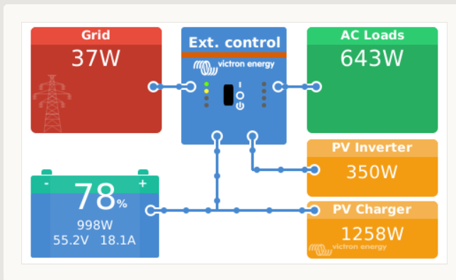
My system is VenusGX + Multi II + MPPT + Liion Battery + Batrium BMS (connected via CAN-Bus). Everything has been updated to the latest version of firmware.

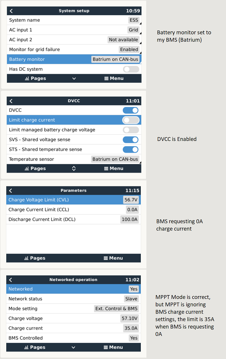
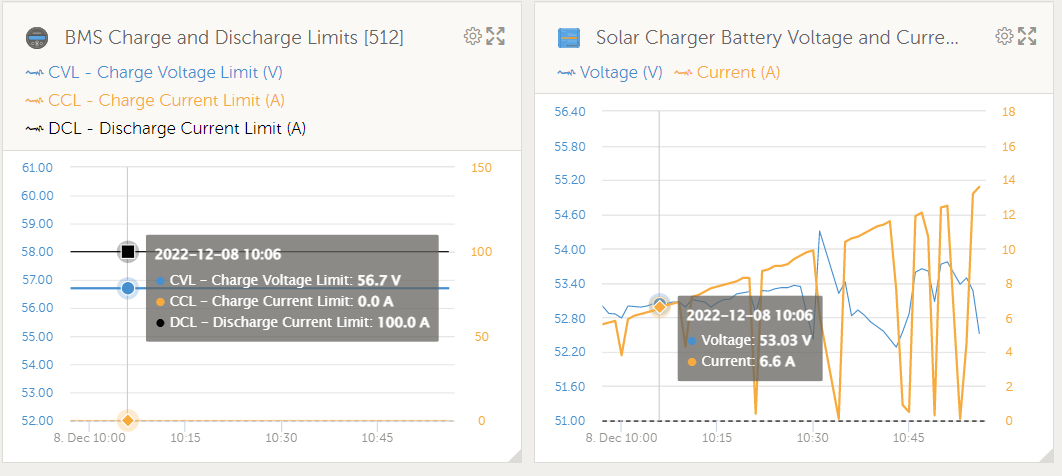
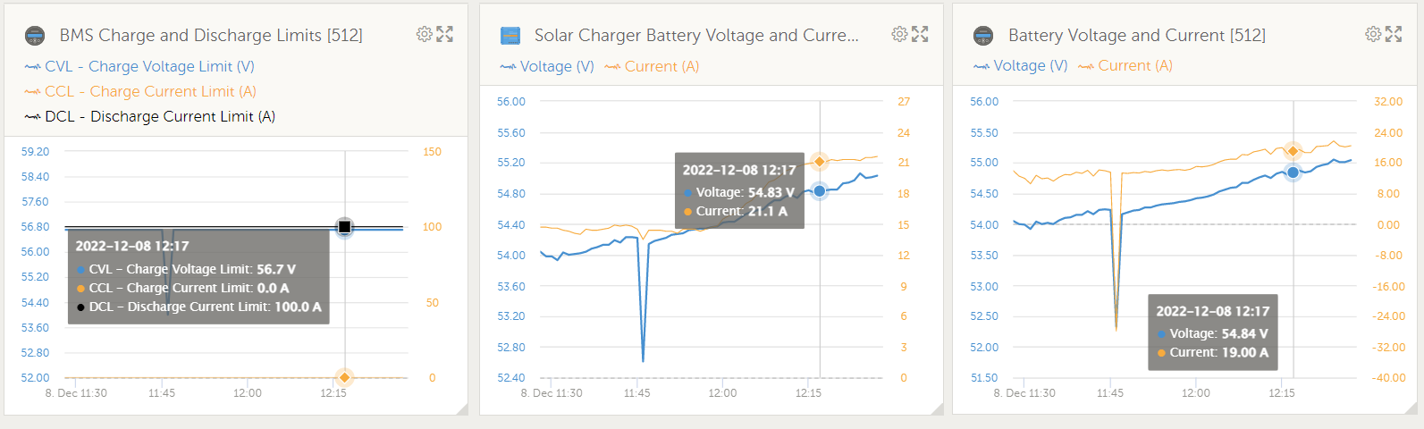
Batrium BMS has been selected as Battery monitor in the VenusOS, DVCC has been enabled. The problem is that the MPPT is ignoring BMS settings and keep charging batteries when BMS request to stop (Charge limit current set to 0A). I've double checked all of the settings, reboot the system (couple of times), but mppt is still keeps charging when it should stop.

Is there anyone with similar system that can do a quick test and request 0A from BMS to see if MPPT will stop?

Any suggestions welcome

venus.png


mppt-charge.png

MPPT ControllersBMSbatrium
venus.png (201.8 KiB)
mppt-charge.png (57.0 KiB)
2 |3000

Up to 8 attachments (including images) can be used with a maximum of 190.8 MiB each and 286.6 MiB total.

5 Answers
nickdb avatar image
nickdb answered ·

The charge current reported in network ops is the maximum the mppt is allowed to generate, not what it is currently producing which is controlled by DVCC.

The battery current reported by the mppt is also used to supply loads, you can see it drops to 0 so it seems to be following the BMS, the ramp up in current and timing correlates to morning and increased amounts of solar generation. You would need to correlate the mppt production to whatever AC/DC loads you are supplying.

3 comments
2 |3000

Up to 8 attachments (including images) can be used with a maximum of 190.8 MiB each and 286.6 MiB total.

mysik avatar image mysik commented ·

Hi @nickdb and thx for your anwser.

The drops to 0 it was when I was restarting the system.

If the current reported in the network is the maximum MPPT is allowed and BMS is requesting 0A, shouldn't this also be 0A on the mppt? I've done little test and changed max charge voltage on the BMS and this change showed up on the MPPT immediately. But when I'm changing current limit mppt is alwasy showing 35A (that is set as max in the MPPT itself).

Mppt is not limiting to support AC/DC load, it is just pumping max current what it can from get from the solar. See picture below (I've included voltage and current reading from battery)

venus2.png

The load is about 2A, but MPPT is taking max from the solar and charging batteries at max it can. The charge current limit is ignored completely. From the test I've done in the mean time I can confirm that the mppt is respecting the charge voltage limit, so why is it ignoring the charge current limit???


0 Likes 0 ·
venus2.png (78.7 KiB)
nickdb avatar image nickdb ♦♦ mysik commented ·
The 35A will never change as it is the maximum limit configured on the MPPT.

If feed-in is enabled in ESS (assuming you're using it) then the charge limit is ignored anyway.

Something else to consider is that the actual battery voltage is well beneath the the CVL which is the point the mppt's would naturally throttle, so having a 0A discharge limit so far from the desired target voltage doesn't seem right.

It has been stated before that the system does not work with a CCL=0A, charging is best controlled by lowering the voltage.

Being an unsupported BMS there isn't much we can do, but I suspect this would work better if the CVL was lower and closer to where it is currently operating (56.7V is quite high).


0 Likes 0 ·
mysik avatar image mysik nickdb ♦♦ commented ·

@nickdb Yes I'm using ESS.

The reason for 0A charge is the battery low temperature. There is number of conditions setup in the BMS to control charge/discharge. The Batrium BMS is changing the charge/discharge current limit based on this conditions. If like in this situation the temperature is below set point it is changing charge current limit to 0A to send information to the system to stop charging. I would expect that controlling current and voltage is two separate things, of course the is correlation between voltage and current but at the end of the day you can control both independently (to the point of course) .

I've done another experiment and I've switch off my MPPT and used only Multiplus II to see how it will behave and guest what... it is behaving as expected and respecting the 0A charge current limit. Working perfectly to the BMS settings (it is only using enough power to support AC/DC load). So the problem is somewhere in the MPPT control side.

0 Likes 0 ·
mysik avatar image
mysik answered ·

Hello again

@nickdb have a look at the current situation:

venus2.png

Grid point set to 50W

BMS requesting 0A (no charge due to low temperature)

but MPPT is at max and charging with over 18A


venus2.png (61.4 KiB)
4 comments
2 |3000

Up to 8 attachments (including images) can be used with a maximum of 190.8 MiB each and 286.6 MiB total.

nickdb avatar image nickdb ♦♦ commented ·

What are your ESS settings, is any feed-in enabled?

I see you also have a PV inverter.

As an experiment you could remove that from the equation.

CCL=0A does work, my own batteries behave like this when fully charged and all 3 of my MPPT's respond accordingly and only supply loads.

Your MPPT is connected via ve.direct?

As a workaround you could enable "limit charge voltage" and choose an appropriate value, that should stop it pretty swiftly.

0 Likes 0 ·
mysik avatar image mysik nickdb ♦♦ commented ·

@nickdb

Mppt is connected via ve.direct, changing limit charge voltage is not an option because the battery voltage is changing all the time and the stop request from BMS could be at different SOC,

I found where the problem was. Both AC and DC excess feed-in was enabled. I left only AC feed-in on now and Mppt started working as expected. So the problem is somewhere in the software. With the DC excess feed-in enabled, Multiplus should export excess to the grid, but it is not doing that. It is just ignoring the DC side and all MPPT production is going to DC load and batteries, which is really bad and potentially dangerous too. Victron need to have a look at this.

So for now, by switching DC excess feed-in off I'm protecting my batteries, but I'm loosing PV production that I could export to grid and earn some money. So I can't say that I'm 100% happy with the result, but I prefer to protect my batteries an loose some pennies form the export tariff

0 Likes 0 ·
nickdb avatar image nickdb ♦♦ mysik commented ·
There will be a good reason why it isn't exporting.

I would first start with your PV inverter, try get a functional system without it.

Then introduce it back in.

Having an unsupported BMS isn't going to help you.

This stuff works fine with the tried and tested PV inverters and Batteries.

0 Likes 0 ·
mysik avatar image mysik nickdb ♦♦ commented ·

I agree that having not officially supported BMS is not helping, but on the other hand I've tried the system without MPPT (so just VenusGX, Multiplus II, AC coupled PV and batteries) and everything is working as expected. Multi is supporting the load and exporting the excess to the grid and what is the most important - it is not charging batteries when CCL=0A.

If I will have some spare time over the weekend I will do it again this time with MPPT but no PV Inverter. We will see if it will make a difference (my gut feeling is that it will not, but I might be wrong).

0 Likes 0 ·
mysik avatar image
mysik answered ·

Looks like there is a bug in the software!

The MPPT is limiting charge current only if in the ESS/Grid feed-in settings I disable "DC-coupled PV feed-in excess"

If this option is enabled the MPPT is running with full available power, but Multiplus is not exporting this extra power to the grid!!! So rather than supporting the AC/DC load only, it is charging the batteries with all excess power. This is pretty bad as it can irreversibly damage the lithium batteries after only one charge cycle below 0 Celsius. I'm glad I found it now, as this unexpected charge would be very expensive mistake for me.

Something for @Victron to check. It looks like the DC feed-in excess is not working as designed!

Is this a known issue at all? Anyone from Victron can comment, please.

4 comments
2 |3000

Up to 8 attachments (including images) can be used with a maximum of 190.8 MiB each and 286.6 MiB total.

nickdb avatar image nickdb ♦♦ commented ·

It is not a bug. It is documented in the DVCC manual. It is required in order to supply external loads and not limit MPPT production.

The issue is related more to the BMS behaviour, the battery is happy to accept the charge, most likely because of the low voltage due to temperature.

I would still test without the PV inverter involved.

0 Likes 0 ·
mysik avatar image mysik nickdb ♦♦ commented ·

@nickdb why are you thinking that the problem is in the BMS? I see that the BMS is doing exactly what it suppose to do. The temperature is below min set point so it is setting the charge current limit to 0A.

If you connect lithium battery to a charger in -10C it will accept the charge, but it will kill it. You will charge it, but it will be its last charge ever (because of the "lithium plating" the battery will be irreversibly damaged).

My battery was at 78% SOC so I can charge it, but I don't want to!!! BMS is protecting the battery, the temperature is to low and BMS says DO NOT CHARGE! not because the battery is at max charge, but because it is not safe to do so. It is the same situation if the battery is to hot, you don't want to charge it regardless if it can accept the charge or not. If BMS says DO NOT charge then the charger need to stop.

The same system without MPPT is behaving as expected, respecting all BMS current and voltage limits, no problem whatsoever. So again, why do you think that BMS is at fault here?!?!

BMS is saying do not charge, mppt is set to export excess dc coupled power, so I would expect that the multi will take all the power from the mppt (of course Multi power output apply here) and send it to the grid, but it is not happening.

So to summarize.... BMS is doing what it should, MPPT is doing what it should, Multi is NOT doing what it should.

DC-coupled PV excess feed-in is not happening, and you saying that this is the BMS fault? How come?

It looks like a system bug to me!

0 Likes 0 ·
nickdb avatar image nickdb ♦♦ mysik commented ·
It may not be the bms but it could be contributing. The mppts will produce load if they believe they should. A pv inverter affects the ac supply and is also feeding back. Grid supply issues can cause all sorts of strange behaviour, hence the suggestion to remove variables and see what works.

With strange problems it helps to peel back the layers, keep it simple and then build it back up again.

This is a tried and tested solution so there will be something external affecting it, it just may take some work to find it.

At least your batteries are safe now, loss of efficiency aside.

0 Likes 0 ·
cotje avatar image cotje commented ·
Thanks for mentioning this detail about the DC-feed-in. I could replicate the behavior in my setup!! The MPPT keeps charging as hard as it can (while not honoring the BMS charge curve), and only once the battery is full the MP will export it to grid > so DC-feed in works only if it cannot charge the battery anymore.

Maybe it's not a bug, but a cannot-do situation! I would expect it to honor the BMS charge value and the MP should export/invert the remaining excess power, but as it seems this cannot be done on DC-side. That would explain what is happening.

Anyone from Victron who can help us understand?


0 Likes 0 ·
cotje avatar image
cotje answered ·

@Mysik DVCC manual makes me think it's working as designed:

  • Note: When DC-coupled PV feed-in excess is enabled with ESS, the DVCC system will not apply the DVCC charge current limit from PV to battery. This behaviour is necessary to allow the export. Charge voltage limits will still apply.

    Charge current limits set at the individual solar charger device settings level will also still apply.

3 comments
2 |3000

Up to 8 attachments (including images) can be used with a maximum of 190.8 MiB each and 286.6 MiB total.

mysik avatar image mysik commented ·

@cotje... I've enabled DC-coupled PV feed-in excess.... and I'm expecting that this excess will be exported, but Multi is not exporting anything, it is just supporting the loads and allowing the rest current to charge the batteries where the BMS says "NO CHARGE".

If this is designed behavior, then it is fundamental wrong in my opinion, and the option "DC-Coupled PV feed-in excess" is misleading, don't you think?

0 Likes 0 ·
Alexandra avatar image Alexandra ♦ mysik commented ·
@Mysik

You seem to have the opposite complaint to everyone. Alot complain that feedback ignores battery CCL limits.... Where as yours is obeying. The thing is with non official supported batteries/bms is this, things don't always work as expected.

0 Likes 0 ·
cotje avatar image cotje mysik commented ·
Hello Mysik, I think the the MP can only control the feed-in-excess once the battery is full. At least, that is what I see happening in my config with both AC-PV and DC-PV.
0 Likes 0 ·
maureralex avatar image
maureralex answered ·

Hi

The problem is that your BMS is not controlling the Charge Voltage Limit CVL only the Charge Current Limit CCL

One possible fix is to change the CVL in Node-Red through Modbus TCP register 2710, depending on your cell voltages you can then lower the CVL in node red.


2 |3000

Up to 8 attachments (including images) can be used with a maximum of 190.8 MiB each and 286.6 MiB total.