question

cargol66 avatar image
cargol66 asked

Multiplus 48/3000 ESS reliability

Hi,

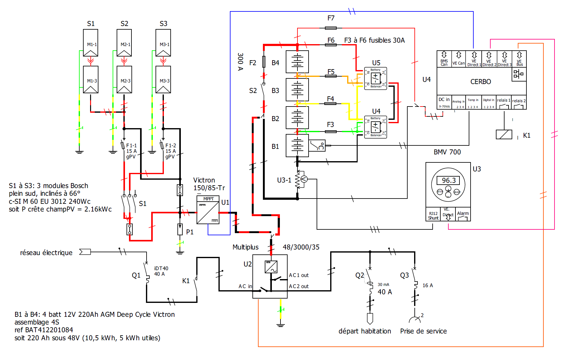
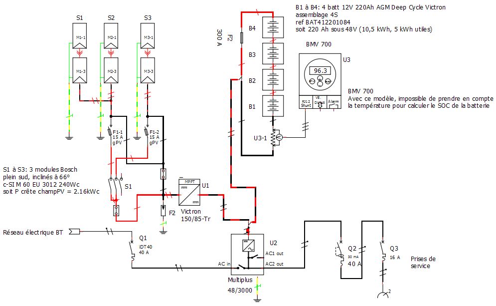
I'm trying to fix battery issue on an ESS system. The schematic is hereafter:

ess-victron-original.jpg

How it works ?

Normaly Q1 is off and the system is running "off-grid"

Q2 is switched on by the user when U1 shuts down because low voltage is reached (batteries are empty) In winter or because of bad weather, Mains supplies the system.

This was working for 2 years, but recently I was called by the user to check his system because he has to switch Q1 on more and more often ...

First check was the battery capacity. so I measure the C20 capacity of each 2 years old 220Ah Victron AGM battery.

Results:

B1 = 212 Ah

B2 = 44 Ah

B3 = 211 Ah

B4 = 207 Ah

Conclusion: B2 is faulty and leads to low batt. state when discharged, limiting the total bank capacity.

I have no idea of the B2 original capacity because il was not measured prior to installation.

So I want to replace B2 by a new one, but I'd like to improve system to avoid a future unbalanced battery pack and of course damaged batteries.

My question: Is it possible to leave Q1 on, and to let the Multiplus choose between mains from Q2, when batterie SOC < 50%, of course Multiplus has to charge batteries lets say up to 80% in the case there is no solar power available from U1.

When battery SOC is > 50% multiplus should not use mains supply but should use the battery to supply system.

I don't want the inverter to inject power in mains.

Is it possible to link components: Multiplus, BMV, and MPPT to exchange temperature, SOC, current, informations in order to drive correctly the system ? (Mplus has only 2xRJ45 I/O connectors)

How to configure the system to do this ?

As BMV 700 doesn't have temperature sensor, I consider to change it by a BMV 712 one.

As VRLA batteries should not be equalized, I consider the use of battery balancers to keep the battery bank balanced

Thanks for your help.


MultiPlus Quattro Inverter ChargerBMV Battery Monitoroffgridsystem design
2 |3000

Up to 8 attachments (including images) can be used with a maximum of 190.8 MiB each and 286.6 MiB total.

2 Answers
nickdb avatar image
nickdb answered ·

You should add battery balancers.

Do you have a Cerbo/GX? You can't have an ESS without one.

This is where you would connect all the devices.

I suggest you read the cerbo manual, specifically the chapter on DVCC.

You can attach additional temp sensors to the cerbo directly as well.

2 |3000

Up to 8 attachments (including images) can be used with a maximum of 190.8 MiB each and 286.6 MiB total.

cargol66 avatar image
cargol66 answered ·

Hi nickdb,

I consider to use a CerboGX device, but several questions about it:

I didn't see the minimal sofware version about BMV 700 to operate DVCC with Cerbo via VE-direct

I'd lke to monitor the battery mid-voltage or each battery voltage. How to use Cerbo GX analog inputs to do it via resistor divider (not represented on schematic)?

I would use Cerbo to reconnect multi AC in to mains supply via K1, in order to supply the system and charge batteries when soc is < 50% and to disconnect mains AC supply when SOC > 80%.

To save battery life, I would also use Cerbo to add mains supply power when multiplus output power is greater than 1500 W. Is it possible ?

Please find the new schematic here after.

1670514613868.png

Thank you for your help.

Bruno.


1670514613868.png (216.2 KiB)
2 |3000

Up to 8 attachments (including images) can be used with a maximum of 190.8 MiB each and 286.6 MiB total.

Related Resources

Additional resources still need to be added for this topic

Victron BMV battery monitors product page

Victron Offgrid page