question

albert avatar image
albert asked

48V LiFePO4: modular, but at which level?

I have been wondering about 48V LiFePO4 battery implementations. I have searched the site but have not found a post addressing this issue, so thought I would post it.


Generally speaking, most 48V batteries that are available on the market for home use can be considered a 2.5kWh – 15kWh module. They usually consist of 16 LiFePO4 cells (in 16s1p configuration, or sometimes 32 cells in 16s2p) and a controlling BMS, where the BMS resides within the module and communicates with the inverter/charger through RS485 or CAN. Victron publishes a list of compatible/supported batteries.


When more storage capacity is needed, 2 or more identical modules are connected in parallel. As the inverter/charger needs to know the status of all the battery modules installed, many manufacturers designate one module's BMS as master, which communicates to the inverter/charger. The master BMS supports a limited number of slave BMSs that are connected to the master BMS.


So, when 15kWh is needed, there is the choice of installing 1 x 15kWh module or 6 x 2.5kWh modules (or 3 x 5kWh, etc). Using only one 15kWh module reduces complexity as there is no BMS – BMS communication required.


A similar solution is not so easy to implement when considering larger systems (say 100kWh), because to my knowledge all manufacturers use the modular approach at the 48V level to achieve higher storage capacities.


Assuming a 10kWh module uses 16 x 200Ah LiFePO4 cells, a 100kWh battery made up of 10 of these modules would consist of 10 x (16 x 200Ah + BMS).

What happens when we parallel at the 3.2V rather than 48V levels?

Rather than using 10 x 48V 200Ah 16s1p modules (each with an internal BMS that need to communicate with each other as well as the inverter/charger), the installer would use 16 x 3.2V 1s10p modules (if available), connected to one external BMS that is sized for the particular application (if available).

I realise that the market for 100kWh batteries is limited, but have been wondering if a 16s10p battery configuration, with a suitably sized BMS,as described above would not make things a lot easier.

Your thoughts are appreciated.

Note that the 100kWh above was arbitrarily chosen as an example to illustrate the point I am trying to get across.


Lithium Battery
5 comments
2 |3000

Up to 8 attachments (including images) can be used with a maximum of 190.8 MiB each and 286.6 MiB total.

Alexandra avatar image Alexandra ♦ commented ·

@Albert

Long parallel setups for cells like that have bad charge/current share so will be most likely why it is avoided.

Much easier to have sets/modules and balance those.

So in short Ohms law.

And there are big batteries in existence controlled by one BMS. In one chunk needing special equipment to move. Blue Novas iESS mega boy, or the slightly smaller 60kwh SSS one. Also expensive to move and transport.

0 Likes 0 ·
albert avatar image albert Alexandra ♦ commented ·

Hi Alexandra,

Thanks for the reply. Not sure if I agree with your explanation though.

I agree that in a bank of unmatched parallel 3.2V cells there is the risk that one cell has higher resistance than the other and can hog current. But bad matching of cells in series (in a conventional setup) will also result in a bad battery, it is just more hidden because the BMS will limit current as soon as the weakest cell reaches the limits configured.


In EV cars the battery is made up of huge amounts of parallel small (e.g. 3400mAh) lithium ion cells. I have no idea how much matching is done in these, but if their quality control requires perfectly matched cells in a bank, then surely this could also be achieved using large LiFePO4 cells?


The Blue Nova battery you linked is interesting, but not scalable. Another 48V Blue Nova battery seems to be made up of 8 units, connected in series (nom. 6V each?). https://www.bluenova.co.za/wp-content/uploads/2020/07/BN52V-920-48k_NG.pdf

Note that the 8 units are + to - connected using busbars, but also have a BMS connection to each unit.


0 Likes 0 ·
Alexandra avatar image Alexandra ♦ albert commented ·

The Blue Novas are one bms. Each box of cells (48v) has balancing system each though and a way to report its status to the BMS and the monitoring.

So really at the end of the day one long line of cells means either:

  • A slower charge to prevent the closer cells from over shooting. (Hence the mention of ohms law). Possibly with a longer absorption to help with balancing.
  • An aggressive balancing system preferrable active so not too much heat is produced/energy lost.
  • Or mutiple charge points on the battery. Which is what BN have sort of set up with the stacks.


I dont know if you have ever opened, or had a way to monitor individual cells as the battery bank charges up. The end cells rise first, and you get sag in the centre ones on discharge. The larger the battery the longer the absorption cycle needs to be if there are the more cells in parallel.

EV charging is very different to home or solar battery setup. It is much harder on the cells hence the shorter life. And why they can be used as second life batteries in solar.

They try get around the parallel issue by running higher voltage so shorter parallel runs.

0 Likes 0 ·
albert avatar image albert Alexandra ♦ commented ·

I agree that the difference in resistance from charger/load to individual cell is a potential problem (I understand Ohm's law), but does not the same occur when you parallel say ten 48V/10kWh modules at the 48V level (rather than at the 3.2V level)?

Unless cables of identical gauge and length, low R busbars, etc. are used to make the 48V parallel pack, you would get one 48V battery to potentially trip over(dis)charge protection circuitry while the others are hardly used.

I am aware of the cabling techniques used to minimise these issues (e.g. connect + to the first unit, - to the last unit, etc). I am just wondering if the added complexity of making a parallel pack from individual 48V batteries (the way most manufacturers are doing) really is worthwhile compared to the simple parallel 3.2V solution (which of course needs a single huge BMS, but that is another issue).


Cosider the following. If you implemented the 3.2V parallel option as follows:

Use a box with a single + and a single - terminal on the outside to make individual 3.2V modules.

Install 10 x 3.2V cell inside the box.

Use individual cables (of equal gauge and length) from the + and - terminal on the outside of the box to each individual cell (i.e. each cell has a dedicated, equal gauge and length cable from the + and - terminal).

This should minimise the problem as there is no "center" or "end" cell.

Add a suitably large (i.e. low R) copper busbar to connect all the cells in parallel (i.e. low R parallel connection and slightly higher R connection to external + and - terminals).

0 Likes 0 ·
Alexandra avatar image Alexandra ♦ albert commented ·


You would need some crazy cable management. And a way to protect from mechanical damage etc during transport.

Imagine that on bigger banks. What is practicable starts to become more important.

And with the cable on first and last battery, the same law applies and the middle batteries are behind in charge. So you cant even have that too longe either.

I guess you can never really get away from it, just find a way to reduce the effect and find a balnce between being perdantic and practical.


0 Likes 0 ·
2 Answers
shaneyake avatar image
shaneyake answered ·

Why don't you want BMS to BMS communication?
There are lots of advantages to a modular system. Eg. Single Pack failure doesn't bring whole system offline, easier to transport etc.

"I realise that the market for 100kWh batteries is limited, but have been wondering if a 16s10p battery configuration, with a suitably sized BMS,as described above would not make things a lot easier."
Market is actually pretty big, most of our comical customers have more than 100kwh.
I am not sure what you mean by easier? Connecting the battery cables is probably less than 1% of the time it takes to complete an install. Physically moving of the batteries inverters and modifying the existing wiring takes the most time outside of installing the Panels. We have actually mostly stopped installing modules bigger than 20kwh because handling becomes a massive problem.

There are batteries out there at are large, FreedomWon makes 48V 100-500kwh batteries.
https://www.freedomwon.co.za/wp-content/uploads/Freedom-Won-Spec-sheet_LiTE-Commercial-52V-Range_Overview-1.pdf
But they literally ship the casing and cells separately and then assemble onsite for most installs.

For systems bigger than 100kwh we typically move to HV packs nowadays. 400-800V 128S1P or 220S1P. But then you have forklift, cranes etc, to move the battery.

2 |3000

Up to 8 attachments (including images) can be used with a maximum of 190.8 MiB each and 286.6 MiB total.

albert avatar image
albert answered ·

Thanks for your replies. I see I have caused some confusion and have not made clear what I meant. I do not mean a single huge battery, but modular at the 3.2V rather than the 48V level.

Perhaps this explains what I mean:

victron-modules.jpg
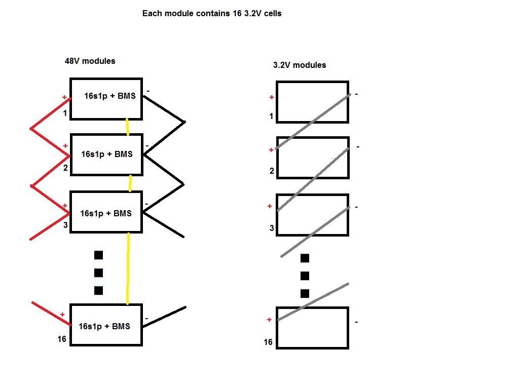
Assume each module above contains 16 x 200Ah 3.2V cell, i.e. they each store 10kWh of energy. That size is reasonable easy to transport and handle.

The difference between the 2 options if that rather than having 16 x 48V/200Ah modules, you could also have 16 x 3.2V/3200Ah modules. The weight of each module is about the same (box + 16 x 3.2V cells), but in the modules on the left the cells are connected in series (16s1p) while on the right they are connected in parallel (1s16p).

The situation on the left requires 1 BMS per module and communication between the 16 BMS's.

The situation on the right requires only a single BMS (much larger of course).


Disadvantages:

As mentioned above of course single point of failure (the huge BMS). To be fair, the master BMS in the 48V system can also be seen as a single point of failure (reconfiguration of the system would be required to take the master module offline, e.g. setting up another module as master).

Much thicker (lower R) cabling between modules

Advantages:

No BMS to BMS communication required, eliminating a potential source of problems.

While cabling between modules needs to be much thicker (lower R), there is no longer a problem is they are unequal length (they do not have to be the same R).


Let's forget about LiFePO4 for a moment, and go back to lead acid where we do not need a BMS.

Assume I want to make a large 48V bank of lead acid batteries. It will be made up of 576 individual 2V cells.

I can make 48V packs (each having 24 x 2V cell in series, so 24s1p) and connect 24 of these 48V "batteries" in parallel

or

I can make 2V packs (each having 24 x 2V cells parallel, so 1s24p) and connect 24 of these 2V "batteries" in series.

or perhaps a mixture.

Is there an inherent advantage or is it up to the preference of the installer?


victron-modules.jpg (77.4 KiB)
2 |3000

Up to 8 attachments (including images) can be used with a maximum of 190.8 MiB each and 286.6 MiB total.

Related Resources