question

gringosailingexpeditions avatar image
gringosailingexpeditions asked

Issues with Lynx BMS going into Safe mode , limiting charging

Hello Id be super grateful if there were any ideas on the below.


We are in a very remote part of the south pacific with almost no internet bandwith about to leave on a 4000 miles passage in the southern ocean to Cape Horn. I have a bout 10 days to try and get this sorted and downloading firmware if needed would need to be done on a satellite terminal, so any suggestions , ideas or thoughts before we start burning up airtime would be great


The system was working perfectly and now The Lynx BMS is doing some weird stuff and not functioning correctly when it get to 100% and hits Absorption mode.


System setup:


Lynx Smart BMS 500 serial number Hq21232t9qp; firmware V1.04
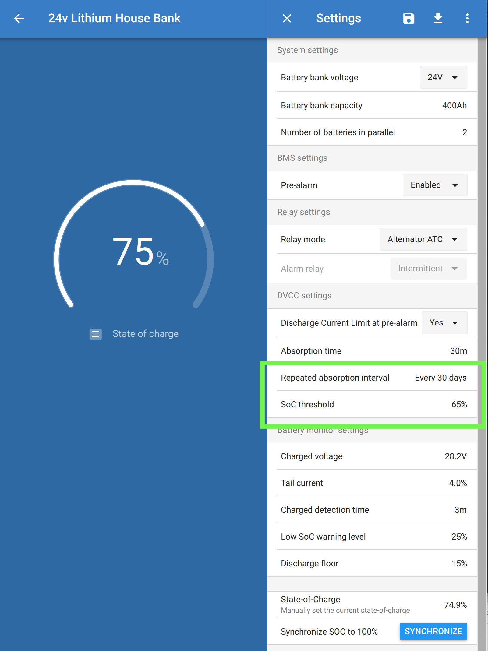
Set to 24V

realy Mode Alternator ATC

Absorption time 5 min ( this was changed so I could get a better undersatning of hat was happening

(3) 200 ah smart Li for a total of 600ah in 24v


Cerbo GX –firmware 2.90-22


Wakespeed WS500’s Firmware v2.5 and then back to v2.43


There are two wakespeed 500 set ups on the boat. One controlling the high out put 24v alternator on the DC Generator and controlling the 120amp 24V second alternator on the propulsion motor.


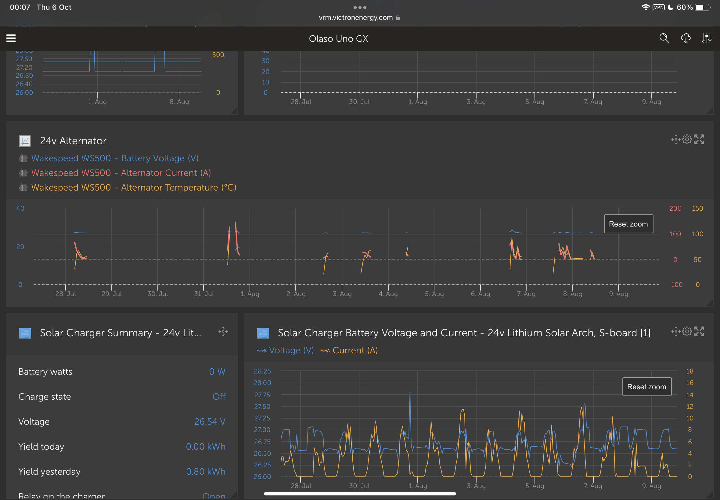
Around when I update to WS firmware 2.5 and GX 2.8 for the enhanced features just before I left Panama for the Galapagos I noticed that while charging once the batteries got to100% and at the end of Absorption time the Wakespeed dumped the field and disconnected instead of going into float voltage @ 27.2V as it had been..

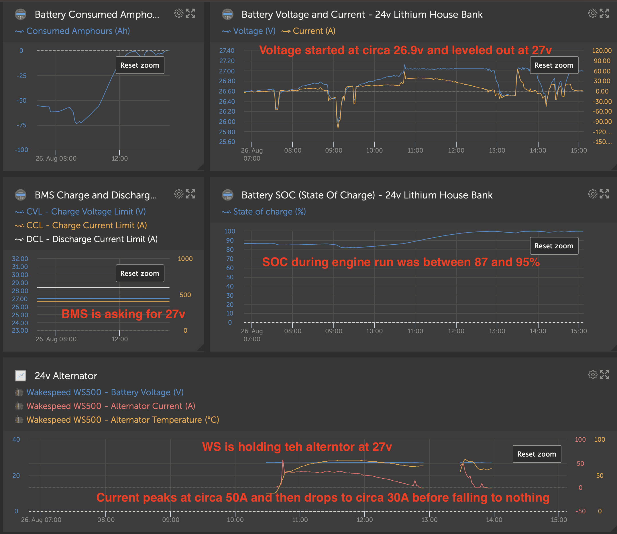
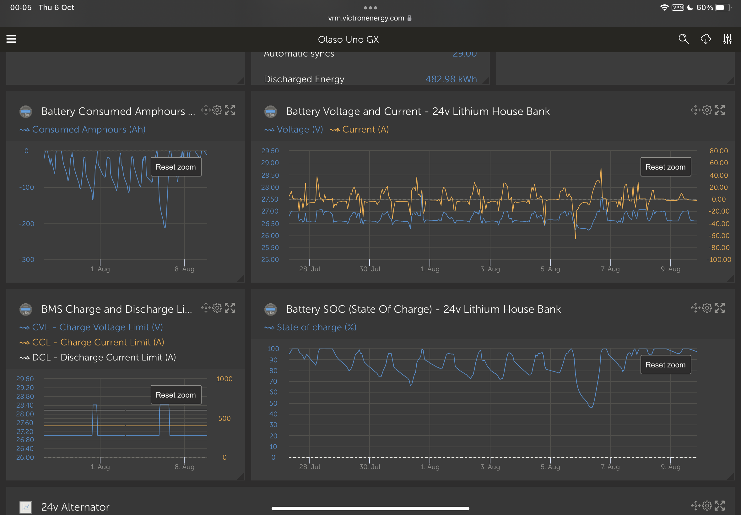
The system charges normally or as you would expect it to getting to 100% SOC , At 100% SOC the voltage increases to 28.4 and the amperage drops from 90 Amp or 180 amps depending on the system to <10 amps, as it should. It then sits there for the Absorption period, until it try to go to float.


If I turn off the motor , and then restart it - the BMS /wakespeed will run but at a very slow pace, and a field of no more the 50% with max voltage of 26.8. When loads are turned on , it slowly ramps up and slowly ramps down to compensate. I was convinced it was the WS 2.5 firmware., I got ahold of Al at WS and we spoke about it , he seemed to think it was the BMS and that it sounded like the BMS was putting the WS into get home mode Or safe mode what ever you want to call it . The fact the voltage output was 26.8 and max field of 50% where the key indicators to him. AL sent me 2.43 via email which had worked previously .. I uploaded 2.43 and it continues to do the same thing.


Whats leads me to think it is a BMS issue is If I turn the power off at the Lynx BMS , and reset the system, then start the engine I can charge normally again with the alternator. The field come straight up and does the amperage, until we get to 100% SOC, and finish the absorption cycle , then the problem shows up again.


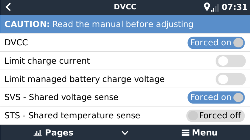
I then noticed it was doing the same thing with the Smart Solar controller that is networked via the GX device that is being controlled by the BMS. For example if I charge the system with the motor or generator to 95 % SOC and let the solar controller run and toke it to 100% it does the exactly same thing. Once the it gets into absorption it shuts down the solar controller , I see voltage 65 +- but no amperage output (displayed on GX display). If I reset the BMS by cycling power , the solar controller starts charging again .


I have someone traveing to the Gmabier this week and they are bringing another BMS, but I would think this has to be software related as it worked and then all of a sudden it didnt.


I did notice at some point the firmware updated on the Lynx BMS , could that be it ?


Is there any way the cerbo GX firm ware could be causing the problem .


Anyone have any thoughts?

lynx bms
2 |3000

Up to 8 attachments (including images) can be used with a maximum of 190.8 MiB each and 286.6 MiB total.

11 Answers
bathnm avatar image
bathnm answered ·

@GringoSailingexpeditions

Your settings look good. I would reset the absorption time back to 30mins.

I think what you are expecting is that every the time you start the engine the voltage should rise to 28.4 and it is not. If the WS500 was in a standalone charge model, this is what you would see as when it is powered up it wants to go through a typical bulk, absorption, float charge as any charge when first started would.

However, this is not what happens when the BMS is sending out CVL and CCL to chargers which are listening. In this mode the BMS has no idea the engine has started. So it controls charge based on time since last 28.4v charge cycle or how low has the SoC dropped.

If you want a traditional charge style, then raise the SoC threshold from 70% to say 95%. Then whenever the SoC drapes below 95% the BMS will send a CVL of 28.4 and all chargers will drive to that voltage until the BMS resets CVL to 27v.

The Lynx Smart BMS manual is worth a read…

“DVCC controls compatible devices via Lynx Smart BMS and a connected GX device. Charging current and voltages are set automatically, thus Bulk, Absorption and Float algorithms are no longer used. Charging or discharging are stopped at low or high cell voltage or low temperature.”

Further so is the DVCC section of the Cerbo GX manual

”Example 1 - Managed CAN-bus batteries For example, in systems with an Managed CAN-bus BMS battery connected, the GX receives a Charge Voltage Limit (CVL), Charge Current Limit (CCL), Discharge Current Limit (DCL) from that battery and relays that to the connected inverter/chargers and solar chargers. These then disable their internal charge algorithms and simply do what they're told by the battery. There is no need to set-up charge voltages or choose the charge algorithm type.”

The issue, if it is happening, related to a load draining the battery rather than the alternator covering i suspect is a configuration issue which we can resolve once the ASCII config is shared.

1 comment
2 |3000

Up to 8 attachments (including images) can be used with a maximum of 190.8 MiB each and 286.6 MiB total.

gringosailingexpeditions avatar image gringosailingexpeditions commented ·

So I first want to thank you for all time you took yesterday and today. There has been a steep learning curve , I built and installed this my self and to be honest ill sleep better tonight as there is one less thing to deal with tomorrow as we prep for the next leg.

I am a" see the light push the button get the banana kinda guy" , so i took all you said , charged , tried a few things watched , changed a few settings and you are right . The system is working as it should., It was my lack of understanding of how it was supposed to work.


I guess the hard thing for me was to wrap my head around DVCC and not the traditional charging profiles. Obviously I want to use the DVCC.......


I guess i still need to understand a bit more about the DVCC and the settings .


Also thank you for everyone else who took the time to respond , with suggestions and observations.

BK


0 Likes 0 ·
ludo avatar image
ludo answered ·

I think you should reset the firmware on the cerbo to the previous version , dvcc could cause exactly this problem. If it's not possible to change the firmware, then disable all dvcc functions, set the mppt and lynx to local.

2 |3000

Up to 8 attachments (including images) can be used with a maximum of 190.8 MiB each and 286.6 MiB total.

gringosailingexpeditions avatar image
gringosailingexpeditions answered ·

we just downloaded the stable GX release 2.91 and it does the exact same thing. ( 23 minutes over satellite ;(


could you explain to me what you mean by disabling teh DVCC and putting the lynx on "local", so uncheck the forced DVCC tab in the cerbo?

Thanks


BK


2 |3000

Up to 8 attachments (including images) can be used with a maximum of 190.8 MiB each and 286.6 MiB total.

ludo avatar image
ludo answered ·

Why did you go "up" on release and didn't go back to the version that worked before?

If it's not possible to "unset" dvcc, just pull the wires connecting cerbo, lynx and mppt.

5 comments
2 |3000

Up to 8 attachments (including images) can be used with a maximum of 190.8 MiB each and 286.6 MiB total.

bathnm avatar image bathnm commented ·
Will not help the Wakespeed pulling the cables. The Wakespeed if configured with a Lynx Smart BMS profile, will be getting it’s charging goals, voltage and current from the Lynx Smart BMS and not DVCC on the Cerbo.


This means that the Lynx Smart BMS is doing something strange regarding charge goals that both the Wakespeed and Cerbo (DVCC) is picking up on and reacting too.

When the event occurred in the Cerbo go into the Lynx BMS device and menu option and then parameters and see what the Lynx Smart BMS is calling for regarding Voltage and charge current. These should be 27v and likely 600A.

0 Likes 0 ·
gringosailingexpeditions avatar image gringosailingexpeditions bathnm commented ·
27v 600a
0 Likes 0 ·
bathnm avatar image bathnm gringosailingexpeditions commented ·

The Lynx BMS is asking for 27v of charge, aka what would have been considered float.

There are two settings in Victron Connect which will cause the Lynx Smart BMS to trigger a charge to 28.4v charge.

1) when the "repeated absorption interval" time has elapsed. So in the screen shot below every 30 days.

2) SoC drops below the SoC Threshold. So in the screen shot below SoC drops below 65%

The other trigger is that the unit has been power cycled.

When the system wants a 28.4v charge (absorption) it only holds it at this for the "Absorption Time", which in teh screen shot below is 30 mins.

I suspect that your system is working correctly. It triggers what you consider a full or absorption charge after a power cycle as that is one of the events that will trigger the charge to 28.4v for 30 minutes (what you call absorption). Once it hits 100%, it will stay at 27v, until such time as the requirement for a 28.4v charge is meet.

If your system is set like mine, with a SOC set at 65% like mine or for every 30 days, then you will not often see charge go above 27v.

What I have noticed is that when the battery is at say 80% SOC, and 27v charge is required the amount of current the Wakespeeds will kick out is a small fraction of the alternators capability. This is because to maintain 27v that is all the system needs to generate, thus the field charge % will be low.

One way to check everything is working is to turn a large AC load on, the Wakespeed should then increase the charge current and field charge % to cover the load.

Please check your Lynx Smart BMS configuration through the Victron Connect App.

If you are still having issues, please share the ASCII configuration you have on the WS500 devices.

Hope that helps.

1664984198041.png

0 Likes 0 ·
1664984198041.png (388.0 KiB)
gringosailingexpeditions avatar image gringosailingexpeditions bathnm commented ·
Mine looks at lot like yours.


What i am saying is once it goes to a full charge , it stops charging completly , not even the "float" votalge to cover loads and usage. after the abso cycle and will never pick up the charge again.no matter how low low the voltage goes.


If i turn off the charge source, (the motor), and turn it back on , it will charge but only in that safe mode , you can watch on teh gx display everything moves very slowly and the field never goes above 50% no matter what the load or the SOC is


Again if i reset the power on the BMS , it will charge at full rate and full field.


Ill try and dig and copy the ASCII, i am using the Victron smart LI profile , unmodified. it shows up on the GS device as WS 500 Smart Li


0 Likes 0 ·
bathnm avatar image bathnm gringosailingexpeditions commented ·

@GringoSailingexpeditions

You say “once it goes to a full charge , it stops charging completly , not even the "float" votalge to cover loads and usage. after the abso cycle and will never pick up the charge again.no matter how low low the voltage goes.”

What do you mean by full charge? Is it that it has cycled to 28.4v held it at that for 30 mins and then drops to 27v? after that it just sits at 27v? If so the system is working as designed.

What do you mean by safe mode following an engine restart? What are you expecting it to do when the engine is restarted? I think you are expecting it to cycle to 28.4v, but if the BMS is not asking for that it will not.

You state “Again if i reset the power on the BMS , it will charge at full rate and full field.”. This is correct behaviour as stated earlier. Following a restart the BMS will do a charge cycle to 28.4V hold for 30 mins and then revert back to 27v.

At any point the question you should be asking and checking is what is the BMS wanting charge wise. What is the CVL (Charge Voltage Limit) or CCL (Charge Current Limit) that the BMS has requested. Can be found under the device in the parameters sub menu.

1665008473828.png

Do I understand correctly that with the engine running, if a load is switched on on the inverter, the alternator does not pick up that load, but that the batteries discharge. Aka a 3Kw load is switched on, that is handled by the battery and not the alternator? If so then you likely have a WS500 configuration issue which the ASCII config will show.

0 Likes 0 ·
1665008473828.png (70.3 KiB)
bathnm avatar image
bathnm answered ·

What are the batteries doing. Use the Victron Connect app to connect to the batteries and see if they are balanced and what state they are in.

When the solar or Wakespeed stop charging after absorption what errors do you get from the Lynx Smart BMS? If the system is going into get home mode or shutting the solar down it must be some form of disconnect that is happening. A reset of the Lynx Smart BMS is resetting that.

Need an idea of what the lynx Smart bms settings are. If you can post screen shots of those and the batteries it would be helpfull.

Maybe when the event happens take a look at the voltage on the Wakespeed feature in port, that will also show you if there is a disconnect event happening.

If the batteries are not well balanced then you could have one cell triggering a charge disconnect which would show what you are seeing. A longer absorption time might be needed to get the battery balanced. During this the charge disconnect may trigger multiple times.

The default Lynx BMS settings have been rock solid on my 24v system with Wakespeed.

4 comments
2 |3000

Up to 8 attachments (including images) can be used with a maximum of 190.8 MiB each and 286.6 MiB total.

gringosailingexpeditions avatar image gringosailingexpeditions commented ·
Hi all three Batteries are perfectly balanced.


The lynx shows no errors on the the GX or the ve connect. or on the flashing lights when the WS disconnects or is in safe mode or when the solar is disconnected


super hard for me to post picutres here.


Setting for lynx BMS :

Pre _ Alarm - Enabled

relay Mode - Alt ATC


DVCC

Dishcarge Current Limit at pre-alarm - NO

Absorption time - 5 minutes ( changed by me - was at factory setting)

Repeated Absorption interval - 30 days

SOC threshold - 70%


Charged Voltage 28.0

tail current 4.%

Charged detection time 3 minutes


All batteries the cell voltages are 3.31 or 3.30. I have never had an issues with balancing since installed.


It was rock solid until recenlty


bk

.


0 Likes 0 ·
gringosailingexpeditions avatar image gringosailingexpeditions gringosailingexpeditions commented ·
could you post a picture of what the screen looks link on the gx under Network services; BMS can Port , where it shows State Rx and TX


Thanks

BK


0 Likes 0 ·
bathnm avatar image bathnm gringosailingexpeditions commented ·

@GringoSailingexpeditions

Is this the screen you want?

1665009777184.png

0 Likes 0 ·
1665009777184.png (111.2 KiB)
gringosailingexpeditions avatar image gringosailingexpeditions bathnm commented ·
yup thanks
0 Likes 0 ·
Trevor Bird avatar image
Trevor Bird answered ·

Hello @GringoSailingexpeditions . We have recently installed a Lynx Smart BMS and Lynx Distributers with the same battery bank as you, 3 x 200Ah, Smart Lithium 24 volt batteries. We also installed Orion chargers and a Quattro inverter Charger. I noticed the Quattro Inverter Charger always indicated it was in Absoption mode but in fact I could tell from the charging profile on VRM that it was in fact in float mode.

I enquired to the forum with this post:https://community.victronenergy.com/questions/156832/quattro-says-its-in-absorption-mode-although-its-a.html

It seems when the CerboGx is upgraded to Version 2.9, the Quattro indicates the charging is "Under External Control" as it is now completely under the control of the Lynx Smart BMS (Via the CerboGx) and the concept of Bulk, Absorption and Float are no longer valid. When the Lynx Smart BMS is connected to the CerboGX, DVCC (Distributed Voltage and Currrent Control) is forced on. That means the MPPT solar controller, the Wakespeed and the Quattro (or Multiplus) chargers are under BMS control. The charging algorithms within these devices are no longer used. All control comes from the Lynx Smart BMS.

We used to talk of 3 stage charging, Bulk(contant current),Absorption(Constant voltage) and Float (Reduced voltage). With these new Lithium Battery chemistries it seems we now charge as fast as we can with as much current as we can and then the charge current tapers off very quickly. When the BMS deems the batteries to be full (as evidenced by the reduction in charging current) the BMS simply tells the charging sources to go away.

I think you are seeing exactly what the new software is designed to do. Charge as fast as possible and then all charging sources simply stop. The Quattro charging status changed from the 3 stage charging algorithm (but never saying it went to float) to "under external control" at CerboGx version 2.9.

I think you should monitor the situation but not be alarmed at what you are seeing. I think your systems are working exactly as they were very recently designed to do.

I hope this helps and I am very keen for someone more knowledgable to advise us of a more plausable story.

Regards,

Trevor

7 comments
2 |3000

Up to 8 attachments (including images) can be used with a maximum of 190.8 MiB each and 286.6 MiB total.

Trevor Bird avatar image Trevor Bird commented ·

@GringoSailingexpeditions just to add some extra information for your confidence please see this small snippet note for the software advice for CerboGx Version 2.90......

We continue to add regionalisation improvements, including the option to configure the UI to show all temperatures in Fahrenheit. Of course, that feature was added to VRM a while ago: we recommend all Americans, Caymanians as well as Liberians to go to VRM and then into the Preferences -> Display preferences menu.

Next, a small change, but one that is good for everyone to know: after the upgrade, Multis and Quattros in a DVCC enabled BMS systems now report their state as External-control- instead of Bulk or Absorption. There is no bulk -> absorption -> float charge algorithm when controlled by BMS, and there never has been. This cosmetic adjustment more accurately displays what is actually happening with the battery charge profile when controlled by a BMS. This change will reduce questions like “Why does my system never go to float …is there something wrong?”


I hope this gives you more confidence.

Regards,

Trevor

0 Likes 0 ·
gringosailingexpeditions avatar image gringosailingexpeditions Trevor Bird commented ·
Hi trevor ,


there is definitely something wrong here. I had similar questions as your when i installed the the system and understand not to be concerned what the multi was saying but The BMS should not disconnect ( dump)t the charge devices , but put them at a ' float " voltage which for the li is 27.2. it was doing this The other thing it is doing is limiting charging when you go to charge again.


none of this happened before. I could take the batteries down to 30% SOC and with out resetting the bms will only allow charging via the WS Can bus connection at 50% field .. thats not right

0 Likes 0 ·
bathnm avatar image bathnm gringosailingexpeditions commented ·

What evidence have you got that the BMS is disconnecting the charge load?


If the Lynx BMS is asking for a 27v charge, and that is what it is asking the WS500 to deliver and the WS500 only needs 50% field drive to get the alternator to 27v then that is all the WS500 is going to request. That does not mean it is wrong.

See VRM charts of the Lynx Smart BMS and WS500. My system is a 24v 400Ah system, which when the engine was started had a deficit of 50A. My alternator can pump out 200+ amps as it is a 5Kw unit.

1664993422673.png

0 Likes 0 ·
1664993422673.png (477.1 KiB)
bathnm avatar image bathnm bathnm commented ·
Just a thought, if you want old traditional charging of flood the battery with as many amps as you can, rather than a battery driven careful charge then remove the CAN connection to the WS500's, and configure them as standalone. Every time the engine starts they will do a bulk, absorption, float charge and your ill find a massive amount of current thrown at the batteries.


P.S Make sure the future in is connected to the charge disconnect signal of the BMS so that if the BMS needs charging to stop, the WS500 can receive a signal to stop charging.

I would not recommend it

0 Likes 0 ·
Trevor Bird avatar image Trevor Bird gringosailingexpeditions commented ·

@GringoSailingexpeditions ..ok if the WS is not responding properly perhaps as mentioned by others, you could remove the Ve.Can connection and operate them “stand alone”. If that is done it is important to use a “Smart Battery Protect” switch activated by the ATC ( allowed to charge) signal from the Lynx Smart BMS. When the BMS deems the batteries to be full, the ATC signal open circuits the Smart Battery Protect so the alternator cannot supply any more current to the battery. It is a more crude way of controlling the charging than the VE.Can connection but will allow the WS500 to go back to Bulk, Absorption and Float without concern for overcharging the battery bank. In all documentation it is stressed it is important to have the Battery Protect to stop charging if the BMS requests so if you do go to stand alone mode on the alternator, this is an important addition.

0 Likes 0 ·
bathnm avatar image bathnm Trevor Bird commented ·

@Trevor Bird

That is not needed. The ATC from the Lynx Smart BMS can be feed into the WS500 through it’s feature in connection. The WS500 will stop charge when the signal on the Feature in port is removed. It stops charge by removing and field drive. This is better for the alternator than removing the load using a battery protect.

The manuals and material on both the Wakespeed site and Victron Site are really good regarding interfacing the WS500 in different modes of operation.

Note even when the WS500 is interfaced via CAN, the Fetaure in is wired through the Lynx Smart BMS relay into the ATC signal. The relay is configured for alternator mode. This means that if the Lynx Smart BMS is about to open the contractor and disconnect, the relay will open a very short time before so that the alternator is unloaded before the contactor is opened and the alternator being disconnected from the battery.

1 Like 1 ·
Trevor Bird avatar image Trevor Bird bathnm commented ·

@Bathnm ..thanks for that good advice. I haven’t installed a WS500 so was not aware of this important and very handy feature. Much better for sure than using a SBP for the reasons you outlined.

0 Likes 0 ·
ludo avatar image
ludo answered ·

Charged voltage should be 28.8, not 28.0

This week this is the 3rd or 4th time I had to write this, I think the victron default is wrong in the latest versions.


5 comments
2 |3000

Up to 8 attachments (including images) can be used with a maximum of 190.8 MiB each and 286.6 MiB total.

bathnm avatar image bathnm commented ·
@Ludo I am not sure it is wrong. Mine is set to 28.4v. My battery returns to 100% SOCc with a 27v charge. The only reason to take the battery uptown 28.4v is for cell balancing, it is not till this higher voltage that the cells start to balance. So 28v or 28.4 or 28.8v is marginal difference. Also at this higher voltage you are not getting that much more capacity into the battery.


If you look at the Victron Datasheet for teh smart lithium batteries then it says between 14v/28v and 14.4v/28.8v (14.2v/28.4v recommended).

My system when it wants a balancing charge calls for 28.4v, not 28.8v.

0 Likes 0 ·

@Ludo

Wonder why you think it is wrong. Please explain.

Charged voltage in the Lynx Smart BMS settings is used to sync the battery monitor to 100%. It has nothing to do with charging. See the Lynx Smart BMS settings.


@GringoSailingexpeditions

I'm not sure if it makes any difference, but try to update the BMS to v1.05, which is the latest.

I can only think of a comms problem, maybe CAN related, which sends the WS into get home mode. The charge parameters for the Lynx Smart BMS are fixed at 27V resp. 28.4V and cannot be changed. Thus the 26.8V must be coming from somewhere else e. g. from WS or another yet unknown and not DVCC controlled charger in your system.

Regarding the same behavior of the solar chargers: as long as they are controlled by DVCC, it is normal that they stop charging once the absorption voltage (28.4V) has been reached and the absorbing time is over. After that they keep the battery at 27V and/or powering your loads. If there is a communication problem between the BMS and the solar charger, Error 67 - No BMS - should be thrown. This should generate a notification in the GX device.

And a last hint: check your battery settings, especially capacity and number of batteries in parallel. The numbers for your system should be 600Ah and 3.


0 Likes 0 ·
gringosailingexpeditions avatar image gringosailingexpeditions Stefanie (Victron Energy Staff) ♦♦ commented ·

we talked about coms problem , but the can bus is working form teh BMS to the WS, as it it is doing what it is supposed to do and i dont get any error light on the WS, it flashes yellow saying it is in can mode.


Al @ WS said the 28.6 was a volatge set by Victron for safe mode when they were developing the interface.


Is there a way for me to download 1.05 and then upload it via sd card on the gx for the Lynx bms.

I have a cable tester and will check the rj 45 connectors this afternoon .


no error code is shown on the solar, i haven't directly looked at that but i believe the voltage was below 27 and it still hadn't kicked on . I can simulate this and report back.

Thanks all for the feed back, i really need to figure this out as we cant be going to the battery box every time we need to chrage again to reset the BMS power ! Im still confused as why this has just manifested itself.

0 Likes 0 ·
Stefanie (Victron Energy Staff) avatar image Stefanie (Victron Energy Staff) ♦♦ gringosailingexpeditions commented ·

@GringoSailingexpeditions

If you don't get any error indications on the BMS, GX device or VictronConnect, it should work like it is supposed to.

I'll ask about the 26.8v but I'm pretty sure that's not the case.

You can download 1.05 from https://professional.victronenergy.com/ (need to create an account, it's free). There is a folder "Lynx Smart BMS" in the firmware menu which contains the firmware file. Download the firmware file. Roughly 195kB ;-)

Now it depends on what device you are running VictronConnect:

VictronConnect on macOS:

  1. Open VictronConnect
  2. Click on your Lynx Smart BMS
  3. From the status view click on the cog wheel to open settings menu
  4. Click on the 3 dots in the top right corner
  5. Click on Product info
  6. Scroll down to Firmware and click on Update
  7. This will open a Finder menu. Once downloaded, go to the folder where the firmware file was saved. Usually the download folder.
  8. Click on the firmware file and then click Open.


VictronConnect on iOS/iPhone

  1. Send the firmware file to yourself by email
  2. Open the email in your iOS device mail app
  3. Tap on the attached firmware file
  4. Scroll left or right to find the VictronConnect icon and tap on it
  5. This will open the VictronConnect device list with a notification that the firmware file has been added to the firmware library
  6. Hit ok
  7. Click on your Lynx Smart BMS
  8. From the status view click on the cog wheel to open settings menu
  9. Click on the 3 dots in the top right corner
  10. Click on Product info
  11. Scroll down to Firmware and click on Update
  12. The firmware library will open. Tap on the firmware file to update.
0 Likes 0 ·
bathnm avatar image bathnm gringosailingexpeditions commented ·
@GringoSailingexpeditions


If you are using version 2.90 or greater of VenusOS on the Cerbo, then the WS500's should be displaying in the device list of Cerbo. This should give you a load of information and error messages.

For example if you pull the feature in line on the WS500, it will give you an error in the Cerbo. Maybe worth testing.

I really am not sure where 28.6v has come from. The safe mode or get home mode which is the default configuration for the WS500 when used with the Lynx BMS is triggered when the WS500 looses CAN communication with the Lynx Smart BMS and it should drop to a charge voltage off 26.4v. This is for safety so that the lithium batteries are not over charged.

If you have yellow / orange flashing LEDs then the WS500's are locked onto the Lynx Smart BMS and following the charging goals it sets.

As shared earlier, you can see these on the Cerbo under the Lynx Smart BMS device or through Victron Connect.

You can also see what the WS500 is doing through the device list on the Cerbo. See the Cerbo manual and WS500 section. It should be showing a Network Status of Slave and State of Ext Control. This also means that the Lynx Smart BMS is driving the charge goals.

From everything I am reading it all looks as if it is working. If not then please share some screen shots if you an of the Cerbo and / or Victron Connect as well as the ASCII configuration you have on the WS500's.

0 Likes 0 ·
ludo avatar image
ludo answered ·

Dvcc controls chargers according to soc, at 28v the soc can be anywhere between 30 and 99.* %


3 comments
2 |3000

Up to 8 attachments (including images) can be used with a maximum of 190.8 MiB each and 286.6 MiB total.

@Ludo You may want to reconsider this.

  1. DVCC controls chargers according to the target voltage (CVL) set by the BMS. SoC doesn't matter (except for the SoC threshold. Based on that it will change CVL).
  2. SoC at 14.0V (or 28V for a 24V system) is >99%, thus can be considered fully charged. It only takes seconds/less than a minute to reach the CVL of 14.2V/28.4V from 14V/28V.
1 Like 1 ·
ludo avatar image ludo commented ·

2.


Depending on the net power you have available it might also take an hour.


I'm living in an RV and continually check all parameters, your data sounds like coming out of a lab with stable parameters.


I know exactly that a cup of coffee costs me o.4% soc, 8 chicken legs on the airfryer 10%.


0 Likes 0 ·
bathnm avatar image bathnm ludo commented ·

@Ludo the screen shots of VRM I showed are from my yacht during 3 weeks of cruising and real world. this is just how the Lynx Smart BMS and WS500 work.

1665011199705.png

1665011267543.png

0 Likes 0 ·
1665011199705.png (504.1 KiB)
1665011267543.png (516.3 KiB)
bathnm avatar image
bathnm answered ·

@GringoSailingexpeditions Just coming back to your original post and these comments.

If I turn off the motor , and then restart it - the BMS /wakespeed will run but at a very slow pace, and a field of no more the 50% with max voltage of 26.8. When loads are turned on , it slowly ramps up and slowly ramps down to compensate. I was convinced it was the WS 2.5 firmware., I got ahold of Al at WS and we spoke about it , he seemed to think it was the BMS and that it sounded like the BMS was putting the WS into get home mode Or safe mode what ever you want to call it . The fact the voltage output was 26.8 and max field of 50% where the key indicators to him. AL sent me 2.43 via email which had worked previously .. I uploaded 2.43 and it continues to do the same thing.

Where are you measuring 26.8v, or what is reporting this? If this is being reported by the Wakespeed, where is the WS500 voltage sense connected?

What voltage are you expecting?

You are concerned that the field drive is only 50%, what is causing that concern? What do you expect the field drive to be?

2 |3000

Up to 8 attachments (including images) can be used with a maximum of 190.8 MiB each and 286.6 MiB total.

ludo avatar image
ludo answered ·

If this "Every time the engine starts they will do a bulk, absorption, float charge and your ill find a massive amount of current thrown at the batteries. " Is a problem the components in the system just don't fit together. I have a max installed charge capacity of 180a, my batteries can handle 400a.


1 comment
2 |3000

Up to 8 attachments (including images) can be used with a maximum of 190.8 MiB each and 286.6 MiB total.

bathnm avatar image bathnm commented ·
@Ludo Please read the various Victron manuals regarding DVCC and what it actually does.


Also please understand the relationship between charge voltage and current. Just because an alternator can deliver 180A, doesn’t mean to say it will. There is a relationship between current and voltage. If the battery is at 26.9v and the charger is pushing out 27v, the current flow will be small. If the battery is at 25v and charger is trying to push 27v the current will be maxed out. Likewise if the battery is at 27v and the charger is trying to deliver 28.4 there will be a higher current. Basically as the charger is trying to hold a given voltage, if the voltage drops more current is pushed to hold the voltage, as the voltage continues to drop even more current is pushed to try and hold the required voltage. To the point the charger can not push any more current and therefore the voltage drops.This is all that is happening in bulk and absorption charges and why when a charger hits absorbtion and holds the voltage the current slowly drops.


The laws of electrons has not changed due to lithium!
0 Likes 0 ·
ludo avatar image
ludo answered ·

Ok, but I needed 14 hours to charge a lead battery from 50 to 100% , c/10 was the standard. My lithium can be charged with 2c, theoretically 20 times as fast.


Al without changing the laws of physics.


And the next generation will be faster, lighter and cheaper.


And, dvcc will not change the laws of physics, I MIGHT consider using it once it's out of beta testing phase with updates coming every week.


My brothers pi with 2.89 large worked fine, with 2.9 not at all, now I'll skip the next few versions keeping my feet on the ground.


You can work as Betatester in the mean time, I only do updates if a problem exists, mit just to take a running system to the grave.


2 comments
2 |3000

Up to 8 attachments (including images) can be used with a maximum of 190.8 MiB each and 286.6 MiB total.

bathnm avatar image bathnm commented ·

@Ludo DVCC is not in beta. It has been around for a long time and for a lot of managed batteries is enabled by default and can not be disabled. What is being added is new managed batteries and default configurations of the system and DVCC to work with those managed batteries. BTW just to ensure no confusion the definition of a managed battery here is one that is connected to the VenusOS typically via CAN and broadcasts CVL, CCL and DCL information to listening charge source and loads. The function of DVCC is to pass this CVL, CCL and DCL information onto inverter/chargers and MPPTs which are note directly connected to the battery, but are connected to the VenusOS through other means such as VE.Direct and VE.Bus.

I have no idea what your system consists of, but even with 2.89 if you have a Lynx Smart BMS, DVCC is enabled and can not be disabled. As already shared in other comments the various CerboGX manual and Lynx BMS manual have really good detail about DVCC how it works and what it does and they are worth a read.

1665037915492.png

My system has taken over 300A of charge, but only when the battery voltage and requested charge voltage is significantly different, aka SOC is say 60% and battery is calling for 28.4v. If SOC is say 80% and battery is calling for 27v the charge current drawn is much less And even less if SOC is 95% and charge voltage being requested is 27v. This all gives better battery life and looks after the batteries better.

2 Likes 2 ·
1665037915492.png (101.2 KiB)
ludo avatar image ludo bathnm commented ·

I don't believe in intelligent batteries, my black boxes have internal BMS and protection, no communication at all. I'm satisfied if soc is 100% before sunset, then I will be able to overcome a rainy week. For a grid application I would always prefer a high Voltage system, 10kw @48v is not acceptable for me as electronics engineer.


400v dc can be directly converted to 230 ac with minimal losses, any industrial converter will work.


0 Likes 0 ·

Related Resources