question

stevect avatar image
stevect asked

Victron Smart Solar Controller temperature compensation

I have a Victron Smart Solar 100/30 controller with the latest updated firmware. My two six volt golf cart batteries have a temperature compensation of -2.8mv/cell/°F.

In the Victron Connect app it says to enter the temperature compensation value for the whole battery which would be -16.8mv. The app limits the compensation value to +-16.66mv so I can't set it properly.


It also appears to be applying the compensation backwards. The temperature at the controller is in the low 60s at night so the controller should be compensating based on that temperature from what I understand. But if I enter a -16.66mv/°F it reduces the voltage instead of increasing it like it should.


Am I understanding all of this correctly or is there something I am missing?

temperature compensation
2 |3000

Up to 8 attachments (including images) can be used with a maximum of 190.8 MiB each and 286.6 MiB total.

3 Answers
klim8skeptic avatar image
klim8skeptic answered ·

The temperature at the controller is in the low 60s at night so the controller should be compensating based on that temperature from what I understand.

The mppt will use the temperature it measures when the PV array starts producing power at the start of the day.

But if I enter a -16.66mv/°F it reduces the voltage instead of increasing it like it should.

Very odd. You are using the - (minus) sign before the number?

2 |3000

Up to 8 attachments (including images) can be used with a maximum of 190.8 MiB each and 286.6 MiB total.

JohnC avatar image
JohnC answered ·

Hi @SteveCT

That upper limit you mention is a conversion from the metric equivalent of 5mV/degC/cell. I've never seen battery makers quote higher than this, and the function is very coarse, so they usually quote in full numbers, like 3, 4 or 5, etc. Convert that to degF and you get something that looks precise, but it isn't really.

I use GC pattern fla batts, which may be like yours. My maker said 4mV/degC/cell, and over my 48V that's 96mV/degC. I just rounded that off to an even 100, cos it's rough anyway.

As already mentioned, the entries must be negative, so charge V increases as Temp drops. And if you don't have a realtime T reading, you may need to compensate your charger V targets to allow for a T rise over the day.

2 |3000

Up to 8 attachments (including images) can be used with a maximum of 190.8 MiB each and 286.6 MiB total.

stevect avatar image
stevect answered ·

So I figured out the limit issue. The .0028 volts is a rounded number from interstate. The actual value is .00277 which equates to 16.66mv. So that problem is solved.


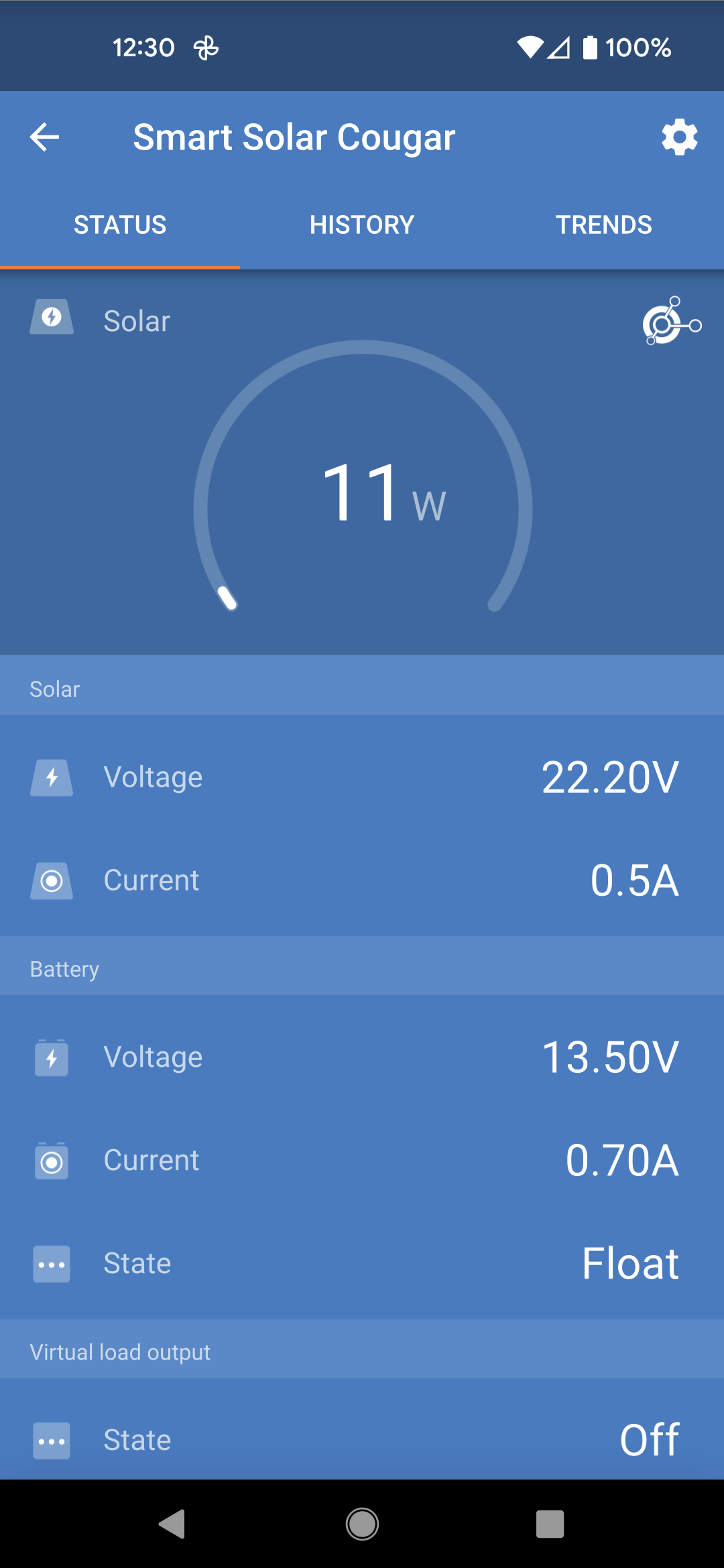
I am still seeing what appears to be a reversed compensation. The temperature this morning was in the low to mid 50s at the controller. When I enter the temperature compensation as a - value the charge voltage is decreased which is the exact opposite of what it should do. When I input the temperature compensation number as a + value the charge voltage rises which is what I would expect with temperatures in the 50s.

I have the float voltage set to 13.4 volts and it's holding it at 13.3 if I input a - temperature compensation number and at 13.5 if I input a + temperature compensation number.

Here are some screenshots.screenshot-20220916-123127.pngImage Caption

screenshot-20220916-123048.png


2 |3000

Up to 8 attachments (including images) can be used with a maximum of 190.8 MiB each and 286.6 MiB total.

Related Resources

Additional resources still need to be added for this topic