question

duswami avatar image
duswami asked

Multiplus II ground relay with essential loads panel

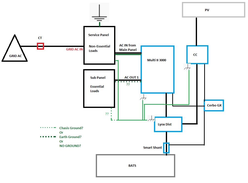
My Grid AC comes into the main service panel as split phase 220/230. My setup has Grid AC going to the Multi AC AC IN via the main service panel (panel is earth grounded with bonded neutrals) through a 50A single pole breaker, as the Multi is the 120v model. I have the AC OUT 1 of the Multi running to a separate essential loads panel (isolated from Grid AC.)

Confused about correct grounding of the essential loads panel. The Multi's Ground Relay opens the relay when inverting, grounding the neutral to the chasis. Currently the chasis is grounded back to the main service panel. Trying to avoid a grounding loop here, but is this as simple as not using the ground conductor in the essential loads sub panel or do I ground the Multi's AC OUT 1 to the grounding bus bar in the essential loads panel? Or do i chasis ground with my other chasis grounds. Or, do i run a new ground to a cold water pipe in basement? Any thoughts or suggestion appreciated.

ground-wiring.jpg

Multiplus-IIGroundingwiring diagram
ground-wiring.jpg (74.4 KiB)
2 |3000

Up to 8 attachments (including images) can be used with a maximum of 190.8 MiB each and 286.6 MiB total.

5 Answers
Kevin Windrem avatar image
Kevin Windrem answered ·

All chassis and safety grounds connects together on all devices.

The neutral is connected to safety ground in only one place. This happens in the service entrance panel for non-essential loads.

The Multi gets hot, neutral and safety ground from the non-essential loads panel. While the multi is using the grid, it passes the hot and neutral to the essential loads sub panel where the neutral and safety ground are NOT connected together.

When the is inverting, the AC input relay opens so there is no longer a connection between neutral and safety ground at the essential loads panel. BUT the Multi also closes its internal ground relay and therefore makes a ground to neutral connection for the essential loads sub panel. This does not create a neutral/ground loop since the AC input relay is open.

Do NOT disable the Multi's internal grounding relay!

1 comment
2 |3000

Up to 8 attachments (including images) can be used with a maximum of 190.8 MiB each and 286.6 MiB total.

duswami avatar image duswami commented ·
@Kevin Windrem that's the answer I was seeking, Thank!

@sharpener @Seb71 Also thank you so much for your input, it helped tremendously!

0 Likes 0 ·
sharpener avatar image
sharpener answered ·

As you haven't said what part of the world you are writing from it is hard to help as this a tricky area and subject to a lot of local variation.

However the earth terminals of the AC In, AC Out 1 and AC Out 2 are all connected together in the Multi (and to the chassis earth stud) so as a general rule it is probably best and simplest to have the earth conductors follow the respective live and neutral connections.

Bonding it all to the water pipes somewhere would for example be regarded in the UK as necessary (but not sufficient), and for island mode operation you would in addition need a separate ground spike, for a fuller treatment of the subject see here.


1 comment
2 |3000

Up to 8 attachments (including images) can be used with a maximum of 190.8 MiB each and 286.6 MiB total.

duswami avatar image duswami commented ·

@sharpener Thanks for the reply. I'm not Islanding, it's an ESS setup hence the separate essential loads panel. I'm in the US, it's split phase from the Grid. Yea, as of right now, the Multi is earth grounded and chasis grounded. What I'm trying to get clarity on is when the ground relay is activated the Multis chasis ground is relevant. If I'm inverting to the essential loads panel does the AC OUT 1 ground float? And, I don't connect that to the ground bus in the essential loads panel, or do I continue the loop with the chasis ground loop on the essential loads panel as in the diagram. My instinct is since the Multi is neutral bond grounded at the Main Service panel, and the chasis ground is meant for grounding when the relay kicks in during inverting then the ground for the essential loads should be on the chasis? Or no!?? Appreciate more clarity!

0 Likes 0 ·
seb71 avatar image
seb71 answered ·

My instinct is since the Multi is neutral bond grounded at the Main Service panel, and the chasis ground is meant for grounding when the relay kicks in during inverting then the ground for the essential loads should be on the chasis?

The ground/PE is (should be) always connected.

The ground relay (when closed) connects the neutral to ground/PE.

4 comments
2 |3000

Up to 8 attachments (including images) can be used with a maximum of 190.8 MiB each and 286.6 MiB total.

duswami avatar image duswami commented ·
@sharpener @Seb71 I spoke with a Victron tech and he said to disable the ground relay function and connect the neutral on the neutral bus and the ground on the ground bus (not bonded as they are bonded at the Main Service panel) and that unlatching the Multi's ground relay will solve the issue. Do you guys concur?


0 Likes 0 ·
seb71 avatar image seb71 duswami commented ·

When the grid is down, Line and Neutral are disconnected from the grid (inside the Multiplus II). So you no longer have that N-PE bond. That's why the ground relay closes (if enabled) when the grid is down.

0 Likes 0 ·
duswami avatar image duswami seb71 commented ·
@Seb71 yes, I understand that, this is why disabling the relay allows the neutral ground bond to remain in place so when the inverter is operating the essential loads panel its fundamentally still grounded through thr main AC panel, correct?
0 Likes 0 ·
seb71 avatar image seb71 duswami commented ·
When the grid is present, the ground relay is open. There is no N-PE bond inside Multiplus II then.
0 Likes 0 ·
sharpener avatar image
sharpener answered ·

I don't think so. Read sections 7.4 - 7.7 of Wiring Unlimited here. The figure on p60 shows the internal relays in the Multi. With ESS, if/when the grid fails the AC input relay L and N contacts open and the inverter is supplying the critical loads in island mode whether you like it or not.

A fraction of a second after this the neutral bond relay closes. This step is necessary because the critical load neutral has now lost the connection to the incoming panel where (as you say above) it was previously connected to earth. If this does not happen your protection against live-earth faults on these circuits is diminished or non-existent. IMHO you should not disable this facility, the provision is there for more unusual arrangements than we are discussing here. If your supplier disagrees please ask him to explain why. I do not understand "unlatching the Multi's ground relay will solve the issue" as I do not think you have an issue which this would solve.

You wrote <If I'm inverting to the essential loads panel does the AC OUT 1 ground float >. No, it should always be tied to system ground somehow, as I said before the easiest and most natural way of doing this (especially if you are using 3-core cable) is to take it to the AC OUT 1 earth terminal.

In the UK we are not allowed to use the incoming supply earth for operation in island mode (in case the supplier disconnects it during repair work), a separate earth spike is required as per the IET paper I linked previously (you should perhaps check locally to see if you need one where you are).

So in my own ESS system the Main Earthing Terminal in the incoming panel is bonded to the ground spike and also the water pipes. There is then a heavy link from the MET to the chassis stud in the Multi, which in turn provides the star point for all the inverter-fed circuits and the battery chassis. This arrangement is logical, hierarchical and avoids any ground loops.

1 comment
2 |3000

Up to 8 attachments (including images) can be used with a maximum of 190.8 MiB each and 286.6 MiB total.

duswami avatar image duswami commented ·

@sharpener So a few things have changed. First, I'm not going to run ESS anymore. Second, I'm going to use programmable relays to control some of the AC usage conditions. Third, I understand what you are saying.

You said "the easiest and most natural way of doing this (especially if you are using 3-core cable) is to take it to the AC OUT 1 earth terminal." This is what I'm doing, and this is the issue I'm trying to clarify. So, based on what you are saying, my AC OUT 1, which goes to the essential loads sub panel is grounded either way, when Grid AC is gone and when Inverting and I leave the ground relay option 'enabled.' Correct? If that's the case, then I'm just connecting the ground conductor from AC OUT 1 to the ground bus bar as usual, correct, as there should be only one neutral-ground bond which is in the main service panel.

0 Likes 0 ·
sharpener avatar image
sharpener answered ·

Some confusion I think remaining between two different issues with the essential loads:

the ground bonding - which is a permanent hardwired arrangement (via the AC Out 1 terminal), you stil need to ascertain if you are required to have a separate earth electrode.

the neutral bonding - which is achieved in two ways, at the main service panel only when the grid is present, and by means of the neutral bond relay in the Multi when the grid is not present and the Multi is therefore disconnected from the main panel (unless you configure it without Loss of Mains detection which I strongly advise you to take local professional advice before doing, see the warnings here).

I have seen your other post about Assistants. It sounds extremely complicated and I don't think you will be able to do it with Assistants. You may be able to achieve some of what you want with Virtual Switch but probably you would need to control the Multi with Node Red or MQTT which is not entry-level DIY stuff. I would suggest you start by implementing ESS and getting to know what it can do. As I have found it is not perfect but you can set it up to achieve zero export and it is a good fit-and-forget solution for most circumstances.

2 comments
2 |3000

Up to 8 attachments (including images) can be used with a maximum of 190.8 MiB each and 286.6 MiB total.

Kevin Windrem avatar image Kevin Windrem commented ·
The purpose of the earth electrode is to drain off static or other small currents that can develop on the chassis of an electrical system. It is NOT intended for carrying large currents and in fact is too high a resistance to do so. The main service entrance will have an earth electrode bonded to the safety ground, usually at the same point where the ground-neutral connection is made. When the Multi switches to inverting and closes it's internal ground relay, a path to earth STILL exists through the non-essential loads panel, so a second earth electrode is not required.


If however the Multi system is disconnected from the service entrance as would be the case when the AC input wiring is disconnected or unplugged (think mobile systems like in a boat or RV), then there is no longer a path to earth to drain static charges. In this case, an earth electrode would be needed.

The purpose of the safety ground connection and bonding it to neutral is to safely return any fault currents from device chassis or structure metal work back to the power source, tripping a circuit breaker.

Even with there is no earth connection, fault currents would safely be returned through the safety ground connection within the electrical system so shock from an electrical hot to chassis fault won't happen.

Interestingly, according to the NEC, safety ground connections on electrical outlets in the US are not required if the outlet is protected by a GFCI. This is because any fault currents that flow would trip the GFCI.

0 Likes 0 ·
duswami avatar image duswami Kevin Windrem commented ·

@Kevin Windrem Thank you

0 Likes 0 ·

Related Resources

MultiPlus-II Product page 

MultiPlus-II Manual

MultiPlus-II 230V Datasheet 

VE.Bus Error codes

Additional resources still need to be added for this topic