question

mikepaterson avatar image
mikepaterson asked

Communication Problems with ET112: Modbus number not being shown

My system is not showing the Modbus Channel and other problems.

Background

My system is a fairly standard ESS set up with Solar PV linked through to Batteries and grid metering via a Multiplus.

  • My set up is as follows:
  • 4kW grid tied Fronius PV inverter;
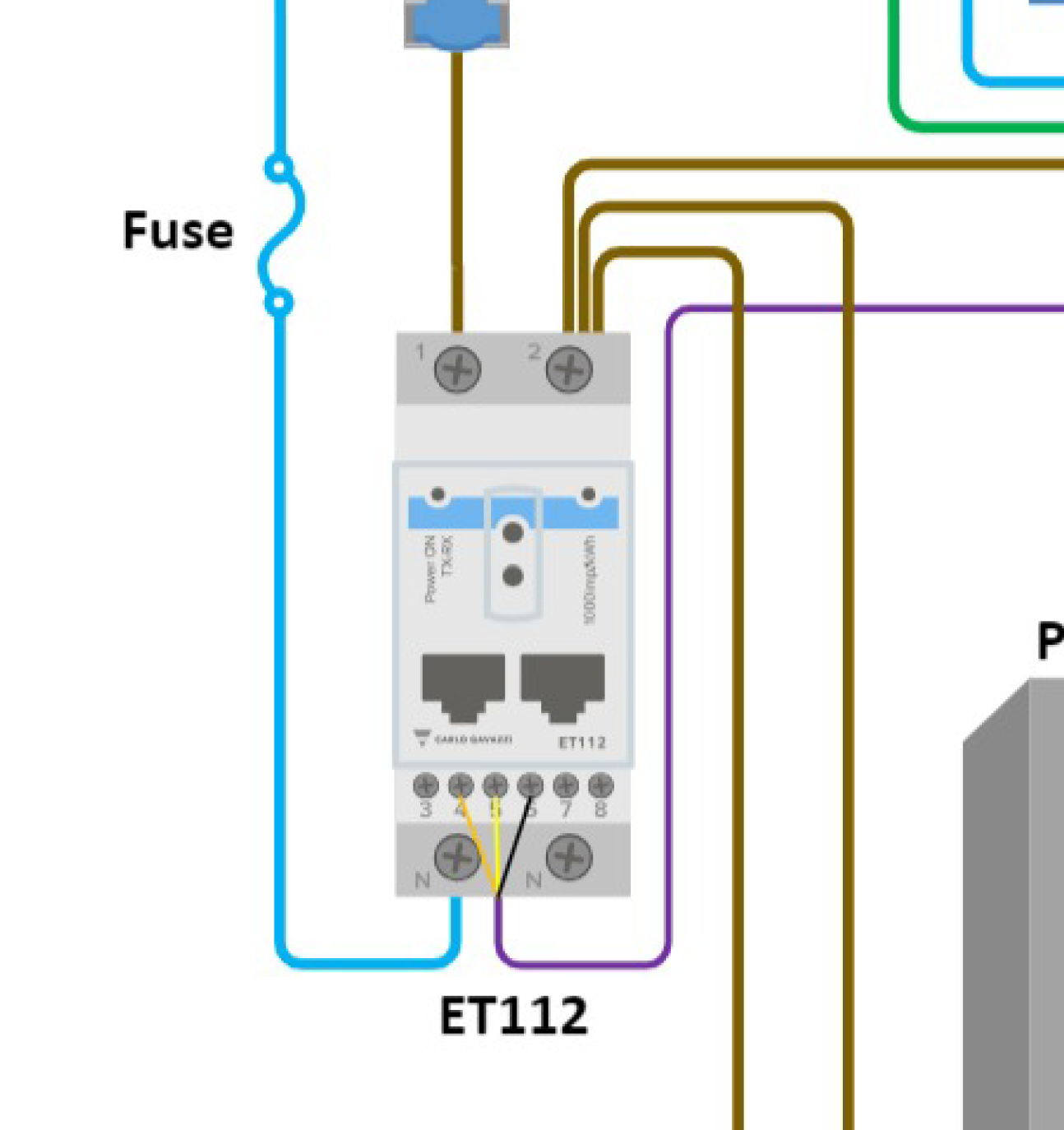
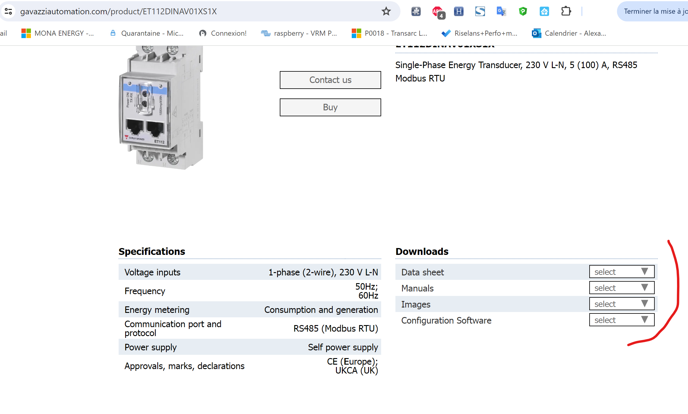
  • ET112 Carlo Gavazzi meter;
  • 3000VA Multiplus@48V ( ~V.xxxx494);
  • 2 x Pylon US3000 Batteries
  • Venus GX on v2.87 with ESS mode.

The Start of the Problems

The system was working well until I started getting "PassThru" errors. After some research this was fixed temporarily by simply unplugging the Victron RS485 lead and plugging it back in again. However the errors returned. I shortened the 5 metre RS485 cable down to the minimum needed of 50cm but this only cured the problem intermittently, and the GX and the ET112 would not communicate. I also tried different combinations of direct wiring to the ET112, and via the RJ45 port. Although I tried termination of the RS485 cable, (by shorting pins 3 & 5 with a cut down Ethernet cable). Given the short lengths of cable this did not seem necessary, and it made no difference.

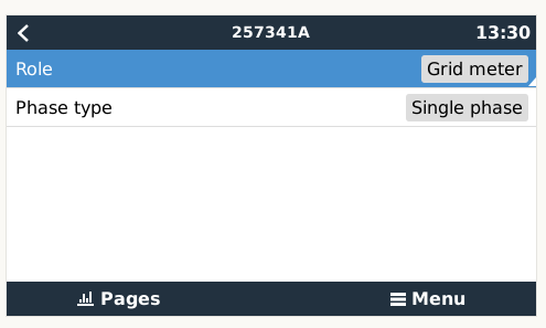
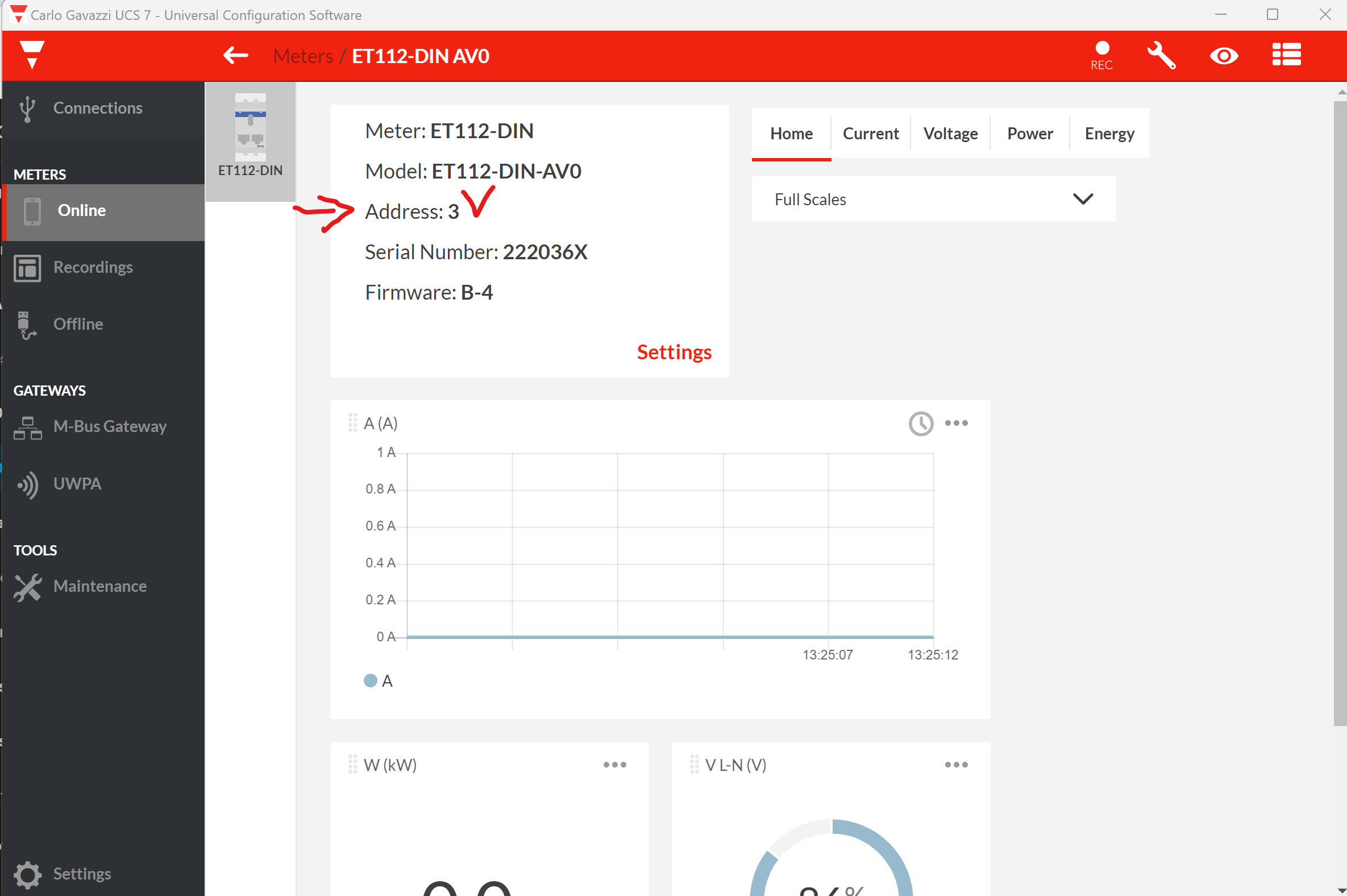
I've now replaced the RS485 cable (for a newer style one). The ET112 is now recognised by the Venus GX, but not exactly as it should. It won't show the Modbus Channel under the "Energy Meters" menu in the GX. It does show the serial number of the ET112 (as checked from the Carlo Gavazzi software), but not the Modbus address, ie 257341A, per screenshot).

257341A 
Role 
Phase type 
Pages 
13:30 
Grid meter 
Single phase 
Menu

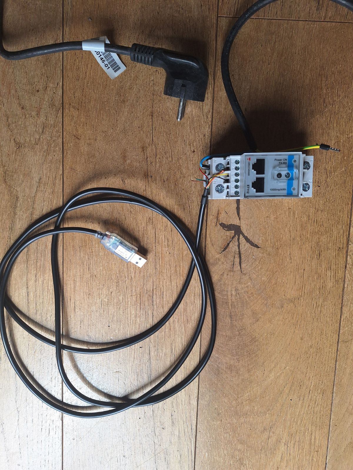
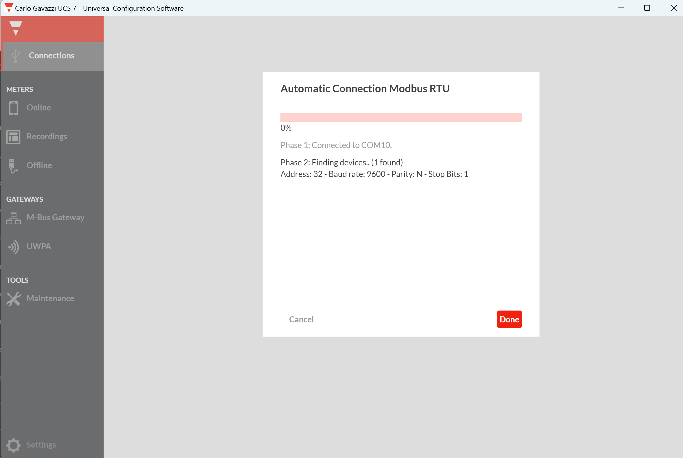
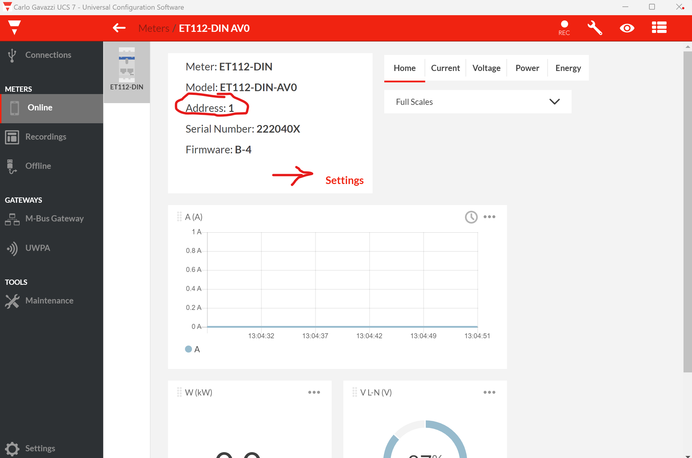
I've managed to communicate with the ET112 directly via the Carlo Gavazzi software, and it appears that the modbus channel that the ET112 is now on is Channel 1 (and not 30, or 32 etc).

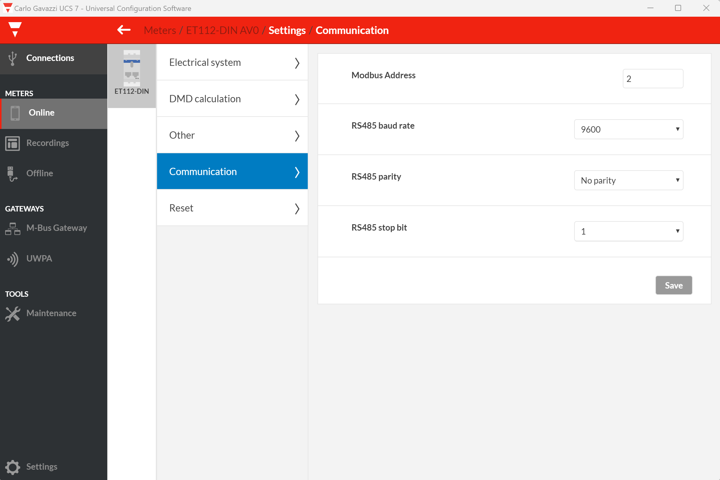
I have tried getting the Venus GX to "forget" the existing ET112 and try to recognise it again when I have manually changed the Modbus channel to 30 via the Carlo Gavazzi software. However the GX and the ET112 will not communicate with the ET112 when the channel has been changed to 30, even after rebooting and "forgetting" the Grid Meter and rebooting again.

I am not sure that the GX has completely forgotten the ET112 even after I press "Remove Unused Devices" (or whatever words it is) under the Device list of the GX. The same serial number of the ET112 still appears in the Settings\Energy Meters section of the GX.

Questions:

So while the system is working, I am not sure exactly what is happening - how do I get it to completely forget the ET112, or how do I get the GX and the ET112 to talk to each other when the Modbus address is manually changed to eg 30?

What is the significance of the Modbus channel number being missing from the GX\Settings\Energy Meters section (even when the Devices List shows there is a working Grid meter)?

I bought a new ET112 in case the meter was the problem, but there is no evidence that the ET112 is at fault. I am reluctant to swap out the old ET112 as this needs me to get involved with the AC wiring and I don't want to if I don't have to.

I would like to get the system to recognise more than one meter eventually as I can then put the spare ET112 meter on the PV side of the set up too.

Thanking you all in anticipation of your assistance.


Mike

Energy Meter
2 |3000

Up to 8 attachments (including images) can be used with a maximum of 190.8 MiB each and 286.6 MiB total.

3 Answers
matt1309 avatar image
matt1309 answered ·

Hi Mike, just checked my venus os and i also dont have the modbus ID in said menu however i do have multiple ET112s one for AC coupled solar and one for the grid.

I didnt mess with IDs in the carlo config at all as long as you use two difference USB to modbus adapters i dont think this is an issue. I believe they only conflict if you use one RS485 to USB adapter and daisy chain the RS485 meters using one RS485 connection.


In settings -> Energy meters I just have two different meters connected, neither show their IDs but like i said they're connected using different RS485 cables (and two different RS485 to USB adapters).

1 comment
2 |3000

Up to 8 attachments (including images) can be used with a maximum of 190.8 MiB each and 286.6 MiB total.

mikepaterson avatar image mikepaterson commented ·

Apologies for not replying earlier. This really helps. The system is now stable following a swap out of the USB to Modbus cable. The original was a proper Victron one so surprising it has shown a fault relatively early. Still not showing the channel number, but it's stable so I am not going to poke about too much. Also just upped it to 3 Pylon US3000C 's.

I do however now have a 'spare' ET112 meter and was looking to utilise that in some way. Matt, you've used it to measure the solar output, and I'd like to do the same. I'm assuming that this will show up in the GX as another source, just like the grid, rather than just a net amount being consumed by the loads. However, stupid question of the day is which way should this be wired up to reflect a (positive) solar output/source? Should the AC cable from the solar mirror that of the grid cable going into the other ET112?

0 Likes 0 ·
mikepaterson avatar image
mikepaterson answered ·

gx-screenshot1.png

Apologies - I should have loaded the screen shot of the GX Settings for "Energy Meter" properly. Now shown. Note there is no Modbus number shown.


Mike


gx-screenshot1.png (11.2 KiB)
2 |3000

Up to 8 attachments (including images) can be used with a maximum of 190.8 MiB each and 286.6 MiB total.

Alexandre PY BLOUCH avatar image
Alexandre PY BLOUCH answered ·

Hello everybody

I had a problem with a PV AC coupling of 2x APsystems photovoltaic generators (DS3-L + YC600 micro-onduleurs) : Be carefull - It's NOT OK // RECOMMENDED for VICTRON ENERGY procedure !!!

capture-decran-2024-04-21-144544.png

Needs : 1x in AC IN of the MULTIPLUS 2-5000 and 1x other in AC OUT (house side)... and 1x on the ENTER AC IN global consumption.

A guy from Victron France (Thierry C @Thierry Cortassa (Victron Energy Staff) told me to install 3x ET112 on 3x USB>RS485 separated cables because the ET112 manufactured by the Italian company CARLO GAVAZZI are programmed by default on a Modbus RTU address in #1... It's CRAZY when you know RS485 RTU works !

https://www.gavazziautomation.com/product/ET112DINAV01XS1X

capture-decran-2024-04-21-145050.png

You could download here the UCS Desktop Configurator software from Carlo Gavazzi Factory (only for Windows PC)...

Install it and lunch it :

You MUST plug AC IN cable for supply the ET112 + connect the RS485 RTU 3x wires Cables like that :

ORANGE = Pin 3

YELLOW=PIN 4

BLACK=PIN 5

image15517.jpg

It is therefore necessary to re-program them in #2 and #3 the following ones.

capture-decran-2024-04-21-132758-com10-usb-trouve.png

capture-decran-2024-04-21-132523-3ieme.png

capture-decran-2024-04-21-130500.png

capture-decran-2024-04-21-130847.png

After re-programmed the Modbus RTU adress to #2, click SAVE and ater auto reboot, you loose normaly the connection... just re-scan and your device is OK with the NEW #3 modbus RTU adress.


2 |3000

Up to 8 attachments (including images) can be used with a maximum of 190.8 MiB each and 286.6 MiB total.

Related Resources