question

dudefinch avatar image
dudefinch asked

Wiring diagram feedback please - Multiplus II GX, MPPT, Pylon LiFEPO4, Consumer unit - UK

Hi people,

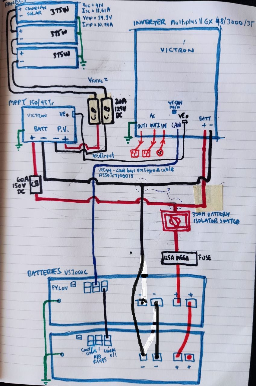
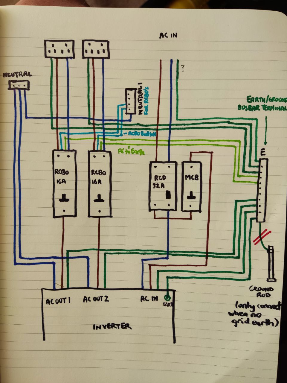
Hoping I can get confirmation that I'm on the right track here. I'm no expert but I've made a couple of wiring diagrams, one mainly showing the DC circuitry and the other expanding out the AC circuits from/to the inverter.

I'm planning on putting all the AC gear into a small consumer unit.

I plan to get the AC in power to the inverter from an existing power socket in the utility room and use the earth cable from it as the earth for the system. If the grid goes down I assume I might need another earth, so could install an earthing rod to connect to in this rare case. I'm based in the UK if it matters.


The equipment I already have is -

Victron Multiplus II 48-3000-35-32-GX

45A Victron MPPT Smart Solar 150-45 - 150VOC Solar charge controller 12 , 24 , 48V

3 x 375W Canadian Solar Mono Half Cell Panels - Super High Power Mono PERC HiKU (only using 3 in this config until I move house soon when I'll expand out with another 7 panels, another inverter and another MPPT)

2 x Pylon 3.5kWh US3000C Li-ion Battery - 48V Lithium

2 x STÄUBLI MC4 Solar Connectors - Pair (Male & Female) suitable for 4mm and 6mm cable only

2 x 20A DC DIN Mount Breaker 125V MCB C curve

Outback DIN Mount Breaker 60A 150VDC

Victron Mega fuse 125A for 48v systems

Victron Mega fuse holder, Stand alone with cover

350A Battery Isolator Switch - Blue Sea E Series 48V

2 x DIN mount rail 35mm 10cm long for DC or AC Breakers

2m x 16mm cable - Large Charge Controller or Inverter to Batteries

100m x 6mm Solar Cable

Victron VE Can to CAN-bus BMS Cable 5 metre Type A

Pylon Batteries DC Cable Pack 25mm

Victron VE Direct Cable 1.8m, straight both ends

Pylon battery Wall Mounting Cabinet PRO


If the AC diagram is ok I'll need to also buy -

2 x 16A RCBO's

1 x 32A RCD

1 x MCD (16A?)

Consumer unit

Ground rod (backup earth)


Also will need several metres of red and black 35mm2 cable to connect the inverter and MPPT to the battery under the counter.


Sorry if I've been a bit long winded here, just like to get all the details down. What do you think, have I got it half right? Any suggestions or comments would be much appreciated.

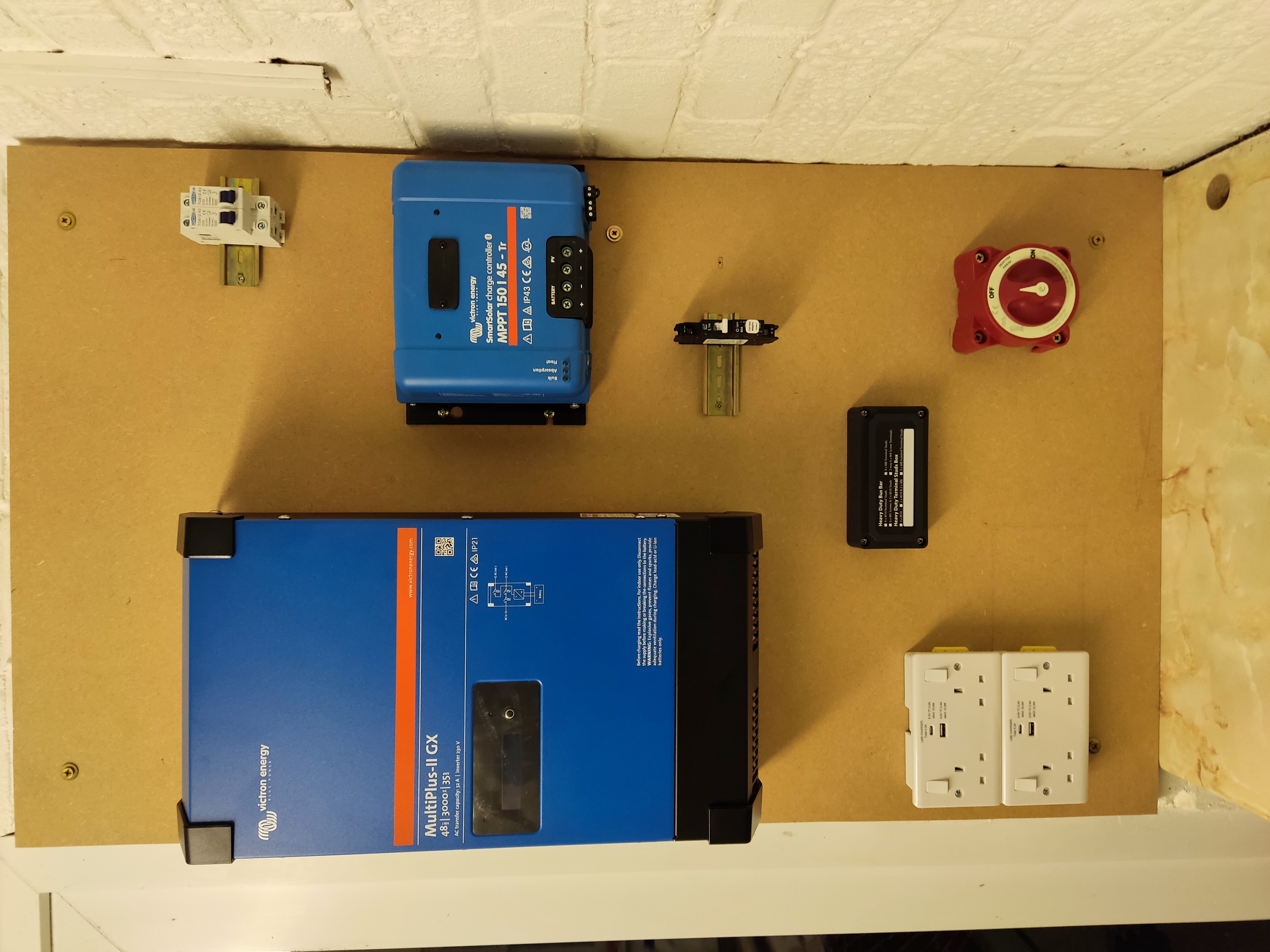
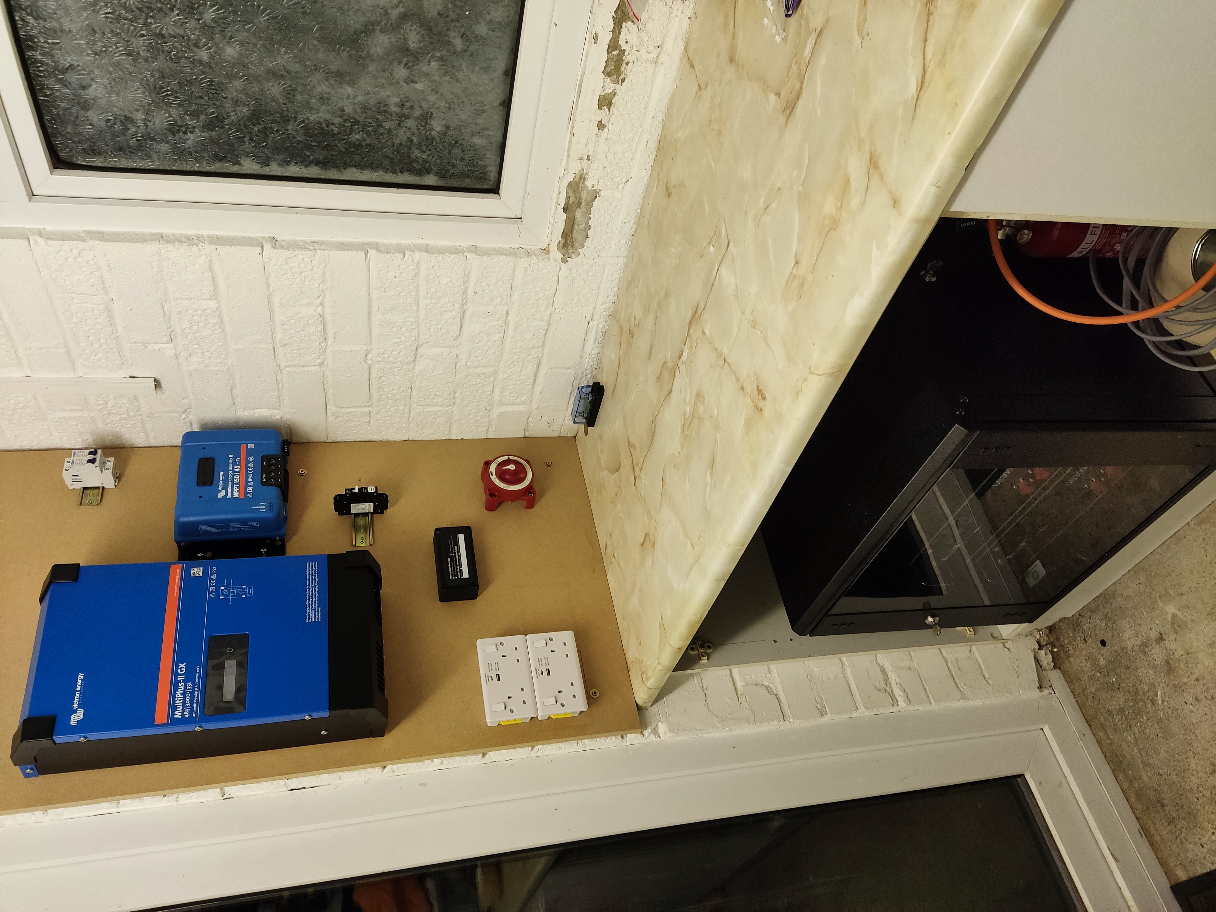
Oh, I've mounted most of the equipment, before realising I might have to move it a bit to make space for the AC consumer unit, unless I put that on a separate board.

Thanks vey much!

solar-battery-system-dc.jpg


solar-battery-system-ac.jpg

solar-battery-backup.jpg

solar-battery-backup-2.jpg

Multiplus-IIMPPT ControllersPylontech
2 |3000

Up to 8 attachments (including images) can be used with a maximum of 190.8 MiB each and 286.6 MiB total.

2 Answers
wkirby avatar image
wkirby answered ·

It looks OK to me apart from the 32A RCD for AC-IN. You'll have selectivity problems here when the grid is available. The 32A RCD may be activated instead of the RCBOs downstream from AC-OUT. If the 32A RCD is activated then the MultiPlus will start inverting and then the 16A RCBO will repond some time later, probably longer than the time allowed for earth fault devices to respond.
Your electrician would be able to offer the best advice here.

1 comment
2 |3000

Up to 8 attachments (including images) can be used with a maximum of 190.8 MiB each and 286.6 MiB total.

dudefinch avatar image dudefinch commented ·
Thanks for taking a look mate, much appreciated. I'll take a closer look at that. Cheers!
0 Likes 0 ·
sharpener avatar image
sharpener answered ·

What is the system going to feed, is it really just two dual 13A sockets?

According to the IET Code of Practice you need a "two-pole isolator lockable in the OFF position" in the feed to the inverter (amongst a number of other things), and I don't think it allows you to take this from an existing socket, all their illustrations show a dedicated circuit and mcb in the main consumer unit. If from an existing ring main it needs at least to be fed from a spur box, and this will limit your AC In to 16A so you will not be able to take advantage of the Multi's 32A pass-through capability.

See here for a discussion of the earthing requirements in the UK, you will need a permanently connected earth rod measuring less than 200 ohms (at least for that part of the wiring which can operate in island mode).

Have you applied to your DNO to do a self-install?


HTH

4 comments
2 |3000

Up to 8 attachments (including images) can be used with a maximum of 190.8 MiB each and 286.6 MiB total.

dudefinch avatar image dudefinch commented ·

Thanks for your help sharpener. So instead of or as well as re needing a two pole isolator lockable in the OFF position? Before the RCD and MCB? I got these requirements from the Victron inverter manual, it didn't mention this but perhaps it's because it's not a UK specific manual eh?

I can live with having to run a dedicated circuit if it means using the full 32A, I'm moving house soon, so the cost of getting that done will be nothing in comparison to moving.

Thanks for link about the earth rod, will check it out.


0 Likes 0 ·
dudefinch avatar image dudefinch dudefinch commented ·
And the 2 x sockets it was to feed was just a start really, I was going to set it up to get things working before I move, but turns out I'll be moving faster than I expected.

How would you set up the outputs?

0 Likes 0 ·
sharpener avatar image sharpener dudefinch commented ·

Rather annoyingly I had a two-pole RCD which is not lockable, and an MCB which is lockable but not two pole! So I have the lockable two-pole rotary isolator after the RCD and mcb, and immediately below the inverter because the box is a convenient way of transitioning from 38 x 16 trunking to the Multi terminals, that seems to be a common arrangement.


On my setup the Multi output goes back to a separate consumer unit which in addition to the RCD and MCB houses a big changeover switch (grid or inverter), and from there to the original CU for the house. But with the 3000VA I doubt you will have enough passthrough capabillity for a whole house, unless you are extremely frugal and cook entirely by gas.


So a logical approach might be to re-wire only essential loads to the output of the Multi and leave the cooker, water heater and most of the power circuits as they are. Much will depend on how your existing wiring is divvied up, unfortunately my predecessor put in lots of lighting circuits but not enough rings so I needed the 5000VA version for the 50A passthrough even though I don't really need the power rating.

HTH

0 Likes 0 ·
dudefinch avatar image dudefinch sharpener commented ·
Sorry only just got around to reading this, but many thanks for your reply mate. It's a bit tricky finding people who know what they're talking about in regards to the AC/DC setup of a solar battery setup, even the company that sold me the gear have given me bad advice. I'll try to modify my circuits and hopefully get some more feedback on what you think. All the best :-)
0 Likes 0 ·