question

mattguy avatar image
mattguy asked

Extra wires to sense current on lynx shunt

Hey all I had no hits the other day asking about the reference voltage of the lynx shunt. I tried asking Victron directly but got the answer that the lynx shunt uses a range of voltages to sense current. Which doesn't make sense to me, but I'm no EE.

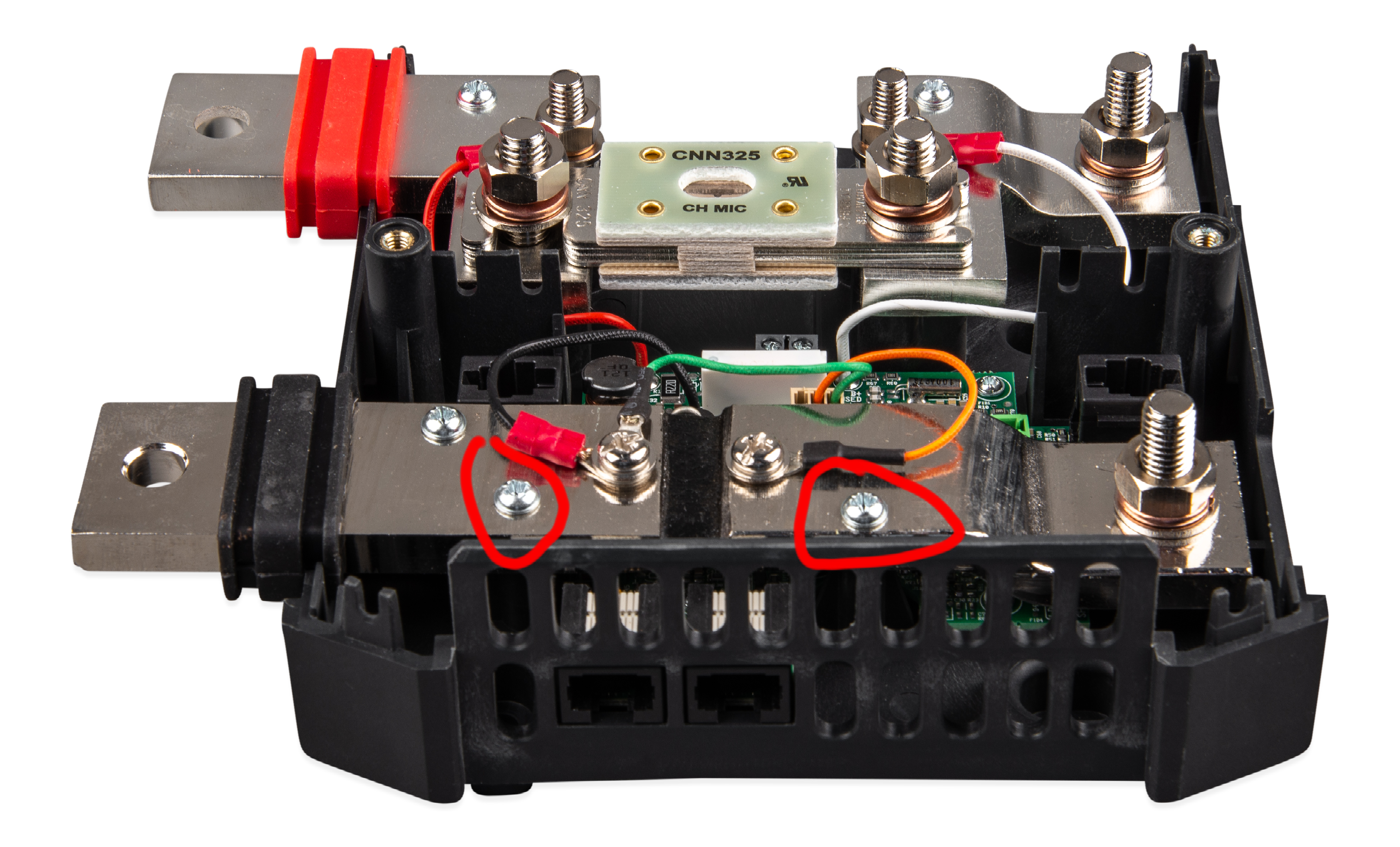
My question is then, does anyone know if it's possible to add an extra current sensing device to the circled locations in the attached photo on the shunt. Essentially using the shunt as a normal 'dumb' shunt for the device I'm trying to hook up? Thanks for any and all help.

lynx-shunt-vecan.png

lynx shunt
2 |3000

Up to 8 attachments (including images) can be used with a maximum of 190.8 MiB each and 286.6 MiB total.

2 Answers
kevgermany avatar image
kevgermany answered ·

Shunts work on ohm's law.

Resistance of the shunt is known. Voltage across the shunt depends on current flowing through it. Circuitry in the unit measures the voltage across the shunt, calculates current and reports it. Hence the varying voltages reply.

It's not clear what you're trying to do but you must have a low resistance/high current draw. You should not connect anything across the internals of the shunt. You risk fire as well as breaking the shunt. If it does continue working, chances are that your actions will invalidate any shunt readings.

2 |3000

Up to 8 attachments (including images) can be used with a maximum of 190.8 MiB each and 286.6 MiB total.

mattguy avatar image
mattguy answered ·

Thanks for your reply.

2 |3000

Up to 8 attachments (including images) can be used with a maximum of 190.8 MiB each and 286.6 MiB total.

Related Resources

Additional resources still need to be added for this topic