question

bm97ppc avatar image
bm97ppc asked

Added a Meter for AC Coupled PV and broke the dashboard

The Setup:

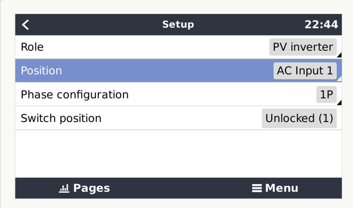
Multiplus II 10KVA, Loads and AC coupled PV on AC IN 1 and I have the optional CT for MP II on the Grid perimeter

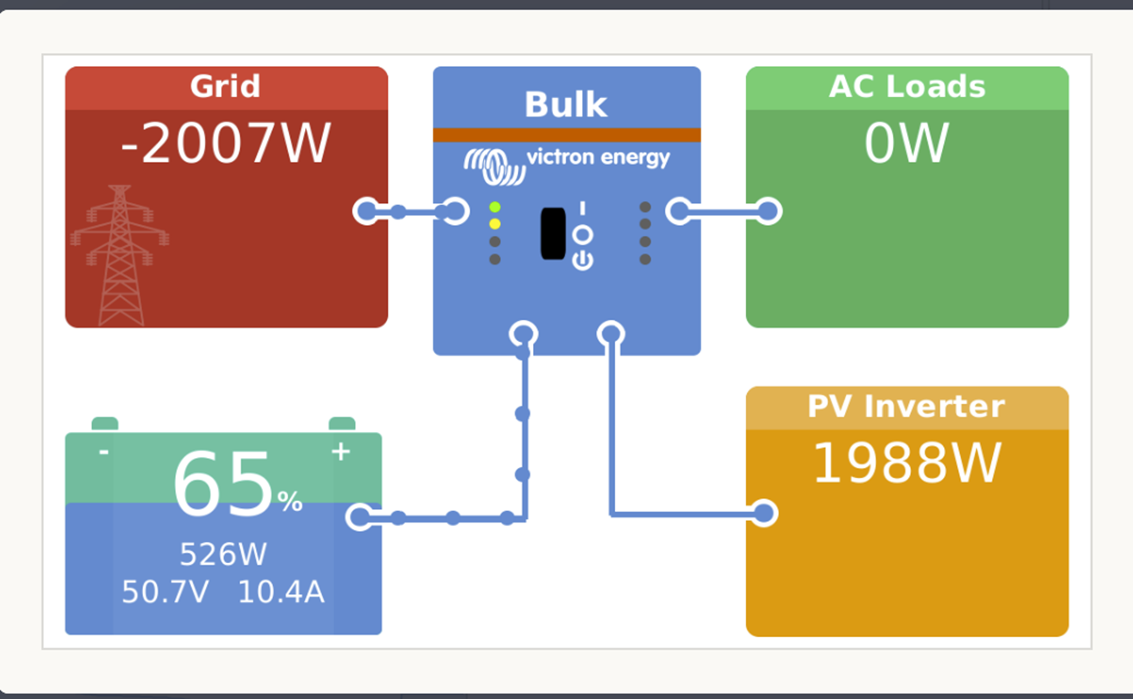
Initially the dashboard was slightly wrong and the PV production was cancelled out by the AC Load, I understand the MP II has no way to show this so the Dashboard was correct based on what the MP II could see. I decided to add a Meter to the PV to be able to see the PV Production.

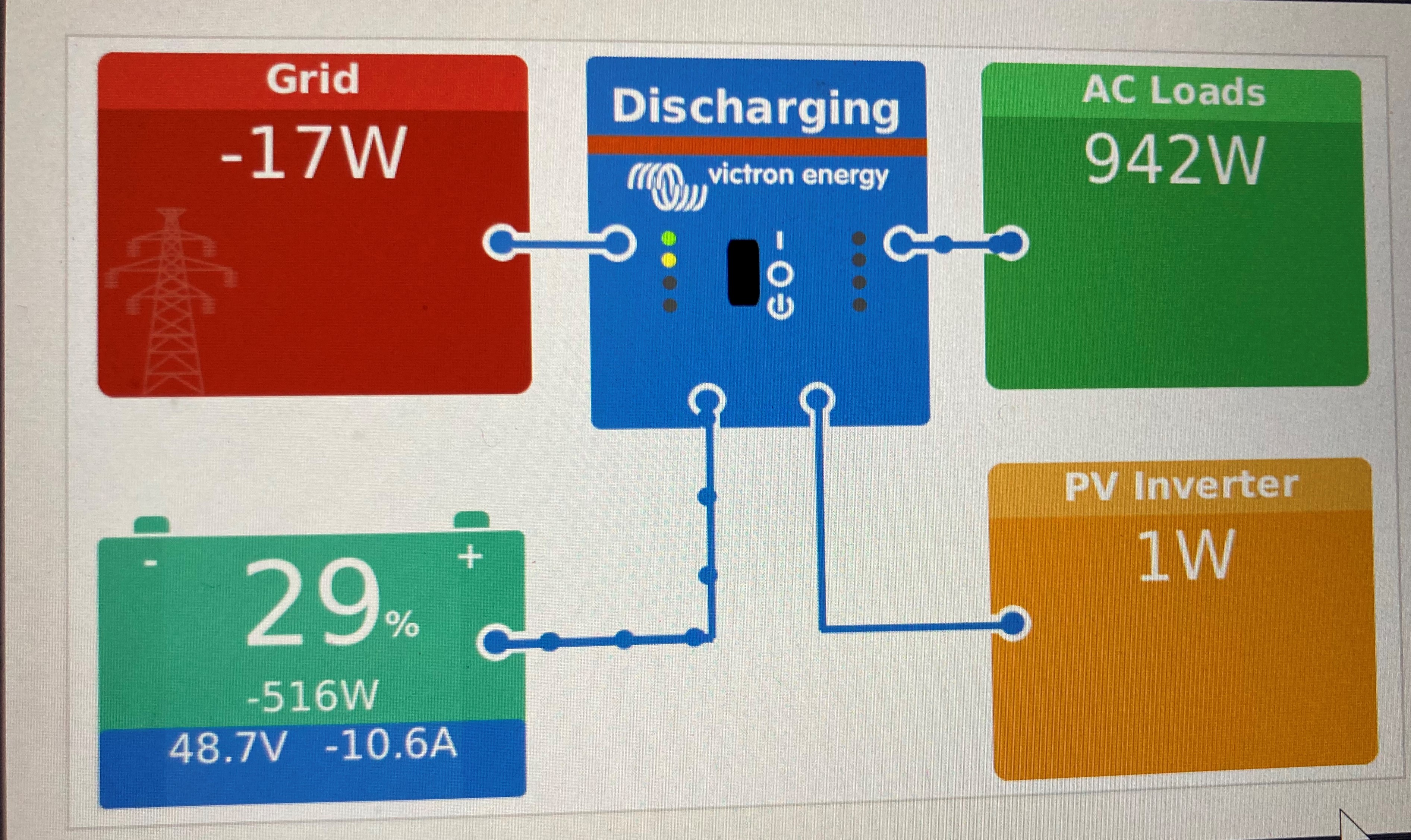
I added a EM24 (ethernet) on the PV Inverter up in the loft. Since installing I am now experiencing

As quoted in 1.2 of ESS Guide

"In particular, without a grid meter:

  • When renewable energy is being provided on the input side, the grid value will be wrong (too low/negative); and
  • The AC Load value shown will be too low (and will show zero where there is a surplus of renewable energy)."

I thought the built in MP II CT (option) and Energy Meter where equivalent however I’m now thinking this is not the case. Can someone confirm this or have I missed a setting somewhere?

ESSEnergy Meter
2 |3000

Up to 8 attachments (including images) can be used with a maximum of 190.8 MiB each and 286.6 MiB total.

3 Answers
shaneyake avatar image
shaneyake answered ·
Try setting the position to AC Out. Because you are using the CT the AC input is actually moved to the CT location, since your PV inverter is not before the CT, it can't be set as AC input.
1 comment
2 |3000

Up to 8 attachments (including images) can be used with a maximum of 190.8 MiB each and 286.6 MiB total.

bm97ppc avatar image bm97ppc commented ·

Thanks, I gave that ago and it seems to have done the trick, I never saw that in the manual.

0 Likes 0 ·
shaneyake avatar image
shaneyake answered ·

The Multiplus-ii CT can only be used to measure the grid connection. Where as the meter can be configured for a variety of uses.

On your GX, have you correctly set the location of your PV inverter?

Can you post some screenshots of the problem and it will also show if your system layout is correct?

2 |3000

Up to 8 attachments (including images) can be used with a maximum of 190.8 MiB each and 286.6 MiB total.

bm97ppc avatar image
bm97ppc answered ·

OK Some screen shots.

1651265150813.png

PV Correct.

AC load should be 2007W (assuming the Charging is normally included in this value).

Grid should be approx 0W (before meter addition when the battery was charging on excess solar it would fluctuate -30W to 30W ish). I assume this is normal.

----------------------------------------------------------------------------------

This one was at late dusk so no solar.

1651266755635.jpeg

All figures seem correct.

-----------------------------------------------------------------------------------

I'll create a Schematic over the weekend but in words:

At the meter the supply forks to 2 Consumer Units (Main CU in house & another in remote location with EV charger and Inverter). The MPII CT is on the Meter Tails before the split.

PV Panels feed into the Main CU.

Inverter in only connected on AC IN.

In the Cerbo GX the EM24 role is PV and is configured to AC IN. 1651269040594.png


1651265150813.png (254.0 KiB)
1651266755635.jpeg (2.1 MiB)
1651269040594.png (83.0 KiB)
2 |3000

Up to 8 attachments (including images) can be used with a maximum of 190.8 MiB each and 286.6 MiB total.