question

vward avatar image
vward asked

VRM SOC should be 100%, but isn’t. Advice please?

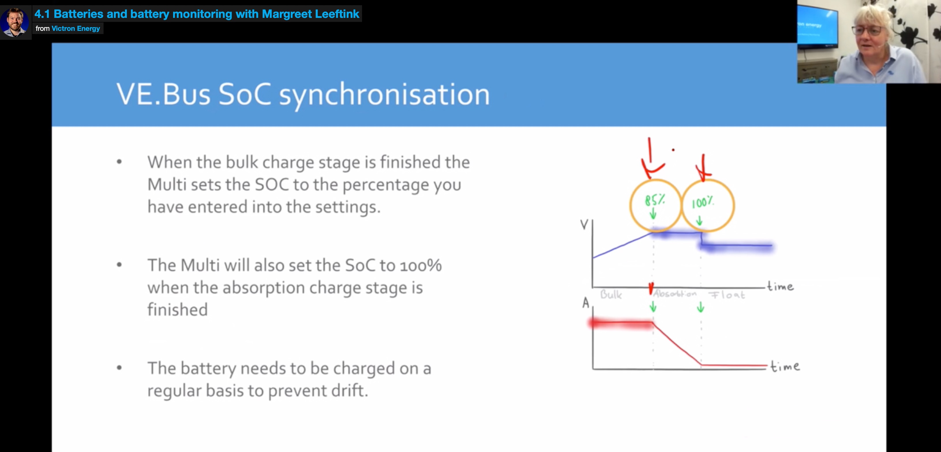
Our VRM is not showing 100% although we tested our batteries with a hydrometer and they are fully charged.


Setup:

Small home, 100% off grid installation.

9.7kW of Solar

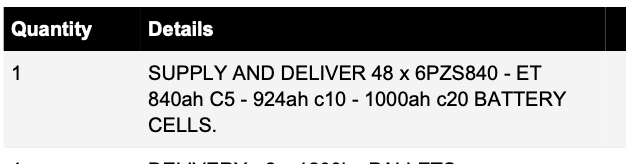
2000Ah Flooded Lead Acid battery bank. 58.8v Absorb and 54v Float as recommended by manufacturer.
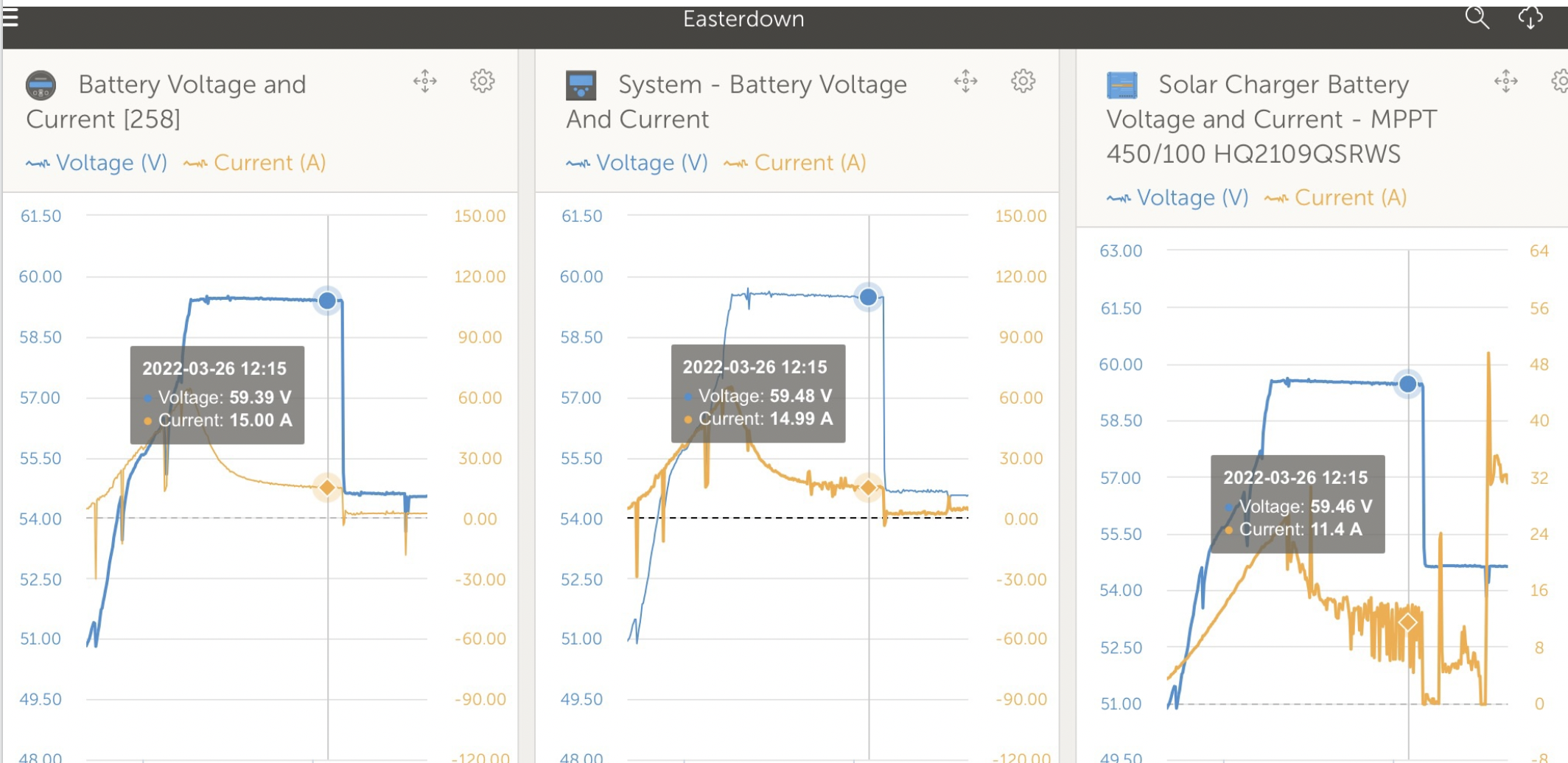
2x MPPT’s

2x 5kVA Multiplus II in parallel

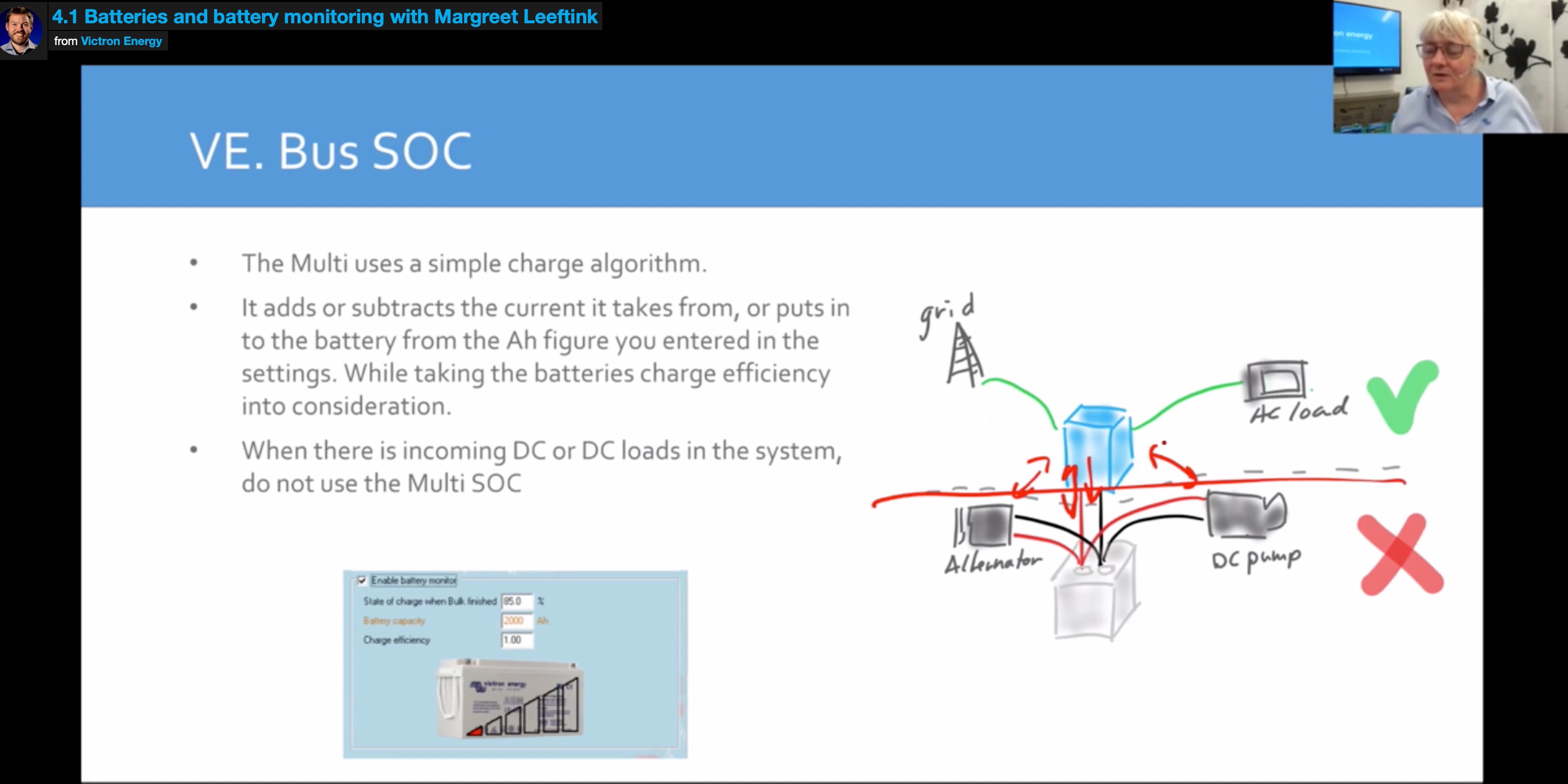
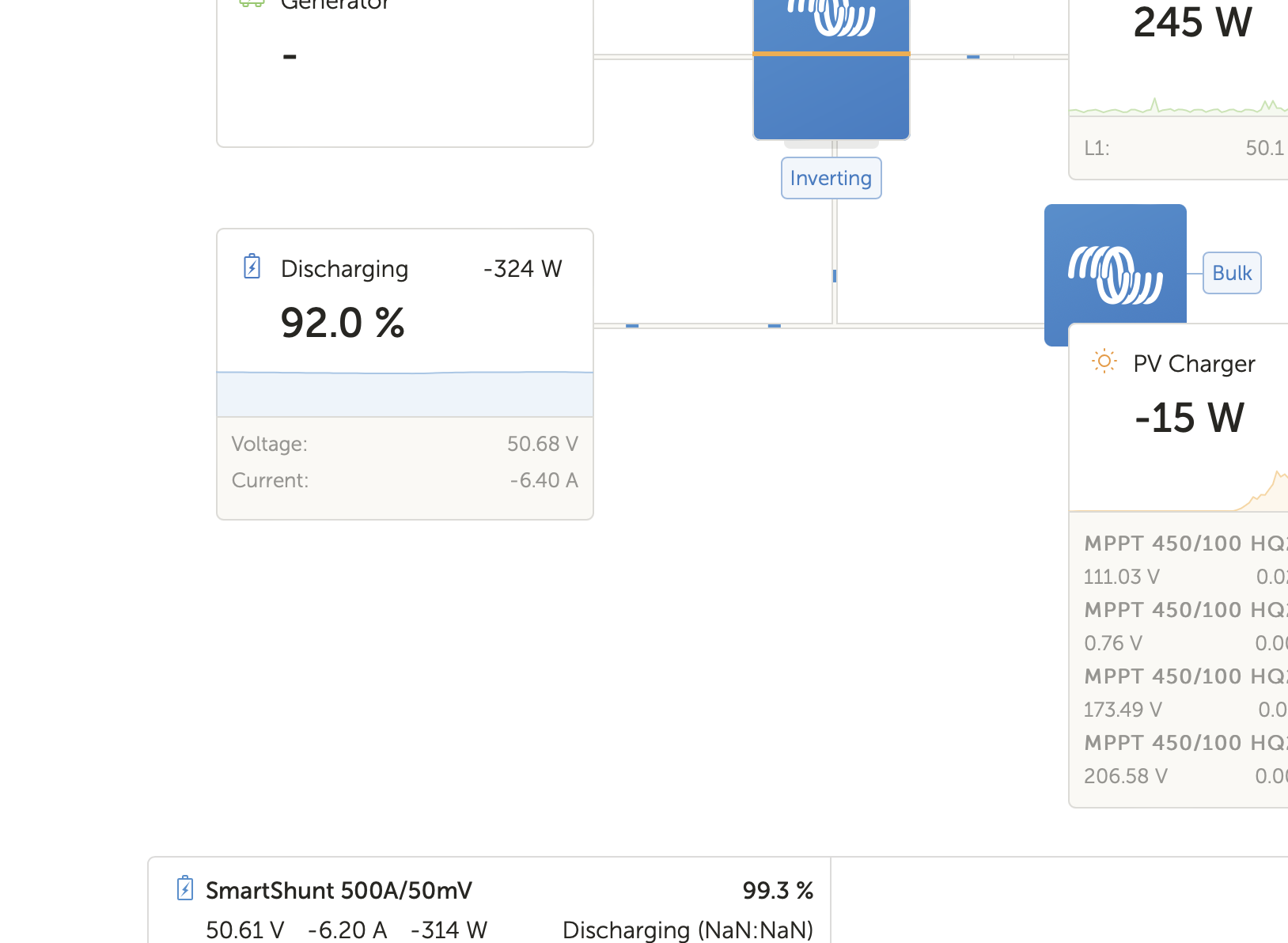
Color Control GX - Using Multiplus as battery monitor

SmartShunt Battery monitor - used the Peukert calculator so that parameter is right. SmartShunt is not networked.


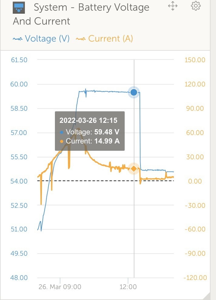
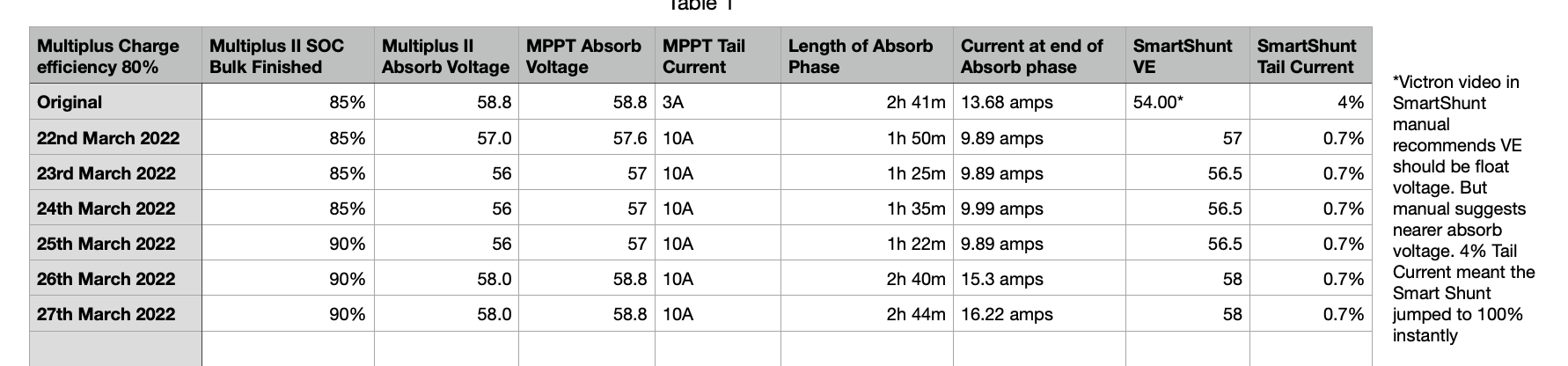
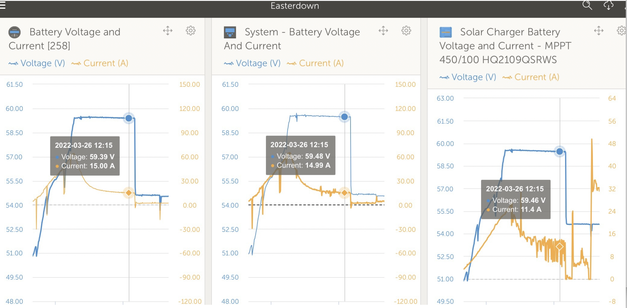
At the recommended Absorption voltage for our batteries (which is 58.8v but we think the voltage below is temperature compensated) the current never goes below 10 amps. It ‘tails’ at about 15 amps. We think we should increase the tail current setting on the MPPT’s above 10amps, but the software won’t allow this.


1649612902626.png

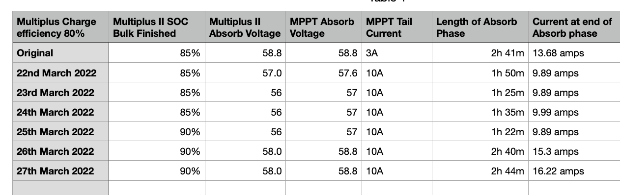
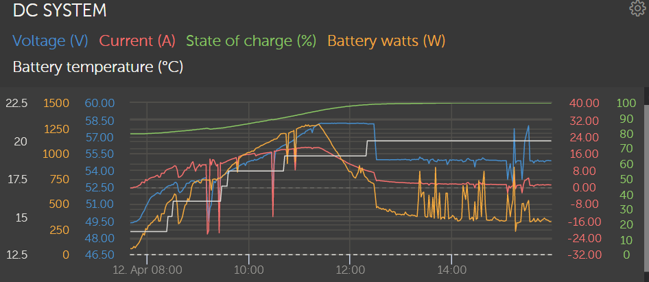
As shown in the table below, over four successive sunny days in March (22nd - 25th) we lowered the Absorption voltage in the MPPT’s hoping that a tail current of 10 amps would occur during our Absorption phase. We understand that when the tail current is reached, the Absorption can end early and go onto the Float phase. As you can see here, that worked. But the MPPT Absorption voltage was much lower than recommended by the battery manufacturer, and the VRM never showed more than 94% SOC on any of the days.

1649612982767.png

We tried almost everything recommended in this thread

https://community.victronenergy.com/questions/39650/how-do-i-get-soc-to-show-100.html

and also in the video found in the Smart Shunt manual, namely:


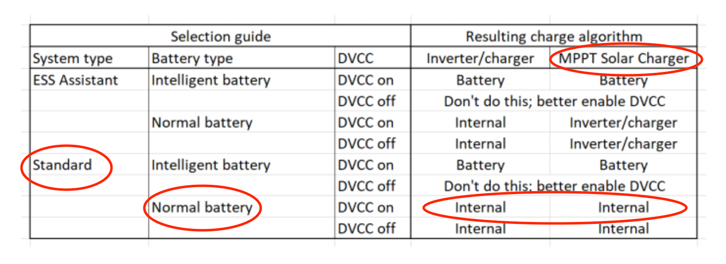
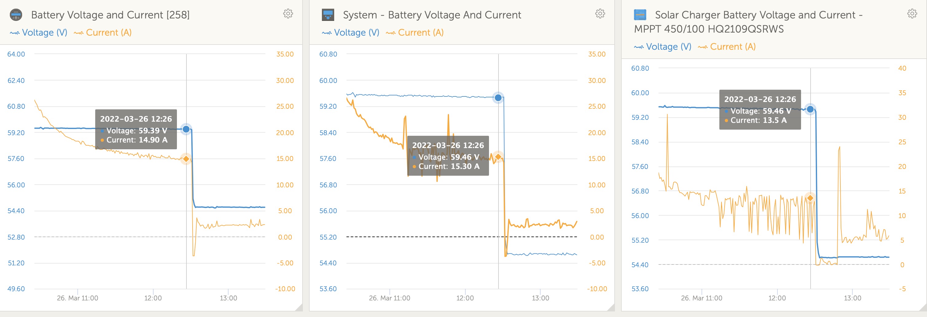
  1. MPPT voltage set higher than Multiplus’.
  2. Charge efficiency in Multiplus’ set to 80%. (our batteries stay well charged)
  3. Raised “SOC when bulk finished” in Multiplus’ to 90%


What will trigger the VRM to show 100%? Not sure if this tail current value is part of the problem?


But over that week the VRM kept saying that the batteries were at most 94% full when the hydrometer clearly showed that the batteries were 100% full. Which they should be after a week of sunshine!

SOCoffgrid
1649612902626.png (313.2 KiB)
1649612982767.png (83.7 KiB)
5 comments
2 |3000

Up to 8 attachments (including images) can be used with a maximum of 190.8 MiB each and 286.6 MiB total.

kevgermany avatar image kevgermany ♦♦ commented ·
I'm confused about the tail current.

Do you have 2000Ah at 48V, or 2000Ah of 12V batteries wired for 48V?

Normal setting for tail current is as a percentage of the Ah capacity at the configured voltage. Starting at 4%. So 2000Ah would give a tail current of 80A.


0 Likes 0 ·
vward avatar image vward kevgermany ♦♦ commented ·

We have 2000 Ah C20. Consisting of 48 2V batteries wired as two parallel strings of 24. If we set the tail current to 80 amps wouldn't our Absorb phase end very quickly?

The graph above is typical - our Absorb phase consistently tails down to 15 amps. So shouldn't that be our tail current? Just to be clear, our SmartShunt isn't networked but it is connected using the cable mentioned by @shaneyake. On the same day the graphs for the SmartShunt, the VRM and one of the MPPT's looked like this:

1649684649913.png

Besides which we can't set the MPPT's tail current higher than 10 amps.

0 Likes 0 ·
1649684649913.png (1.6 MiB)
kevgermany avatar image kevgermany ♦♦ vward commented ·
Just picking up on this. I see there's another query about the capacity further down And to give a simpler example. If you have 2 batteries of 2V and 100Ah each, wired in parallel you have 200Ah at 2V. 4% tail current is 4% of 200, i.e. 8A. If you have them wired in series, you have a capacity of 100Ah at 4V. Tail current is 4% of 100, 4A.

Hence my question, sorry it wasn't clear.

I and the others work on much lower tail currents than the default because of solar charging., but to get an idea of what you are actually seeing we need to understand the capacity of the bank at 48V. This will be 2 times the capacity of the individual 2V cells as you have two strings.

Dividing 2000 by 48 gives individual 2V cell capacity of 41.7Ah. This doesn't sound right. Over the system as described, tail current of 4% would be 4% * 83.4 or roughly 3.3A, split across both strings.

The 15A you measure would indicate a capacity of roughly 200Ah per cell.


0 Likes 0 ·
vward avatar image vward kevgermany ♦♦ commented ·

@kevgermany, Thanks for this. We based our C20 on this information from the invoice for our batteries, and chats to the seller: 1649829978684.png

We thought that if the c20 is 1000ah, then 2x 24 batteries in parallel is 2000ah?

Rightly or wrongly, we divide or multiply by 24, not 48, when we calculate. When I checked with the manufacturer, they recommended an absorb voltage of 2.45 volts per cell. We assume this is 58.8v (2.45 x 24).

When we bought them, the seller told us that our C10 for that configuration is 1848ah. I assume this means the C20 is 2000ah.

Any insights gratefully received!

0 Likes 0 ·
1649829978684.png (23.3 KiB)
kevgermany avatar image kevgermany ♦♦ vward commented ·
Thanks for clarifying. Yes 2000Ah is a good capacity calc, you'll see from other posts that @JohnC will adjust based on usage and charging. More common to use C10. It's never exact.

On tail current, 80A at 4% of 2000Ah is right, but lower the percentage factor is part of the tuning. It has two uses. One for setting State of Charge in a battery monitor, the other for dropping from absorption to float voltage. That it's dropped as low as 15A may be an indication of overcharging.

But @JohnC knows much more than me.

Also make sure you have the correct battery type set, I think you need oPZS. John?


0 Likes 0 ·
5 Answers
shaneyake avatar image
shaneyake answered ·

This sounds like a huge hassle. Just go buy the $10 cable to go from SmartShunt to Color Control GX and all your problems will go away. Victron sells a VE.Direct to USB cable. The multiplus is not meant to be used as a battery monitor if there is anything other than just the multiplus connected to the battery. You are going to constantly have problems.

2 |3000

Up to 8 attachments (including images) can be used with a maximum of 190.8 MiB each and 286.6 MiB total.

Trevor Bird avatar image
Trevor Bird answered ·

Good advice from shaneyake in my view. Prior to doing that however you could watch this very good video about how to install and setup the Smartshunt. You may need to login or get a link to login but it will be worth it.

https://professional.victronenergy.com/online-training/23/

2 |3000

Up to 8 attachments (including images) can be used with a maximum of 190.8 MiB each and 286.6 MiB total.

vward avatar image
vward answered ·

@shaneyake thank you for your suggestion, but the cable you suggest is already installed between our SmartShunt and our GX. @Trevor Bird, thank you, we'd watched both that video and the other by Mr Boonstra. The original SmartShunt VE was 54 volts (the float voltage) but that installation video suggested we change VE to below our Absorb voltage (in our case 58V) instead, because of only using Solar. The full spreadsheet describing our experiment in March is this: 1649684998622.png


@shaneyake you say "if anything other than the multiplus is connected to the battery..." we don't have any DC loads on the battery. Are you saying that Victron do not recommend using the Multi's SOC if MPPT's (DC) are installed? Can you refer me to the manual where it says this? Thank you.

1649685212426.jpeg

Since March, our absorb phase ends every day and we have a long float phase. Yet the Multi's do not set the SOC to 100%.

1649687410377.jpeg

The graph below shows our absorb going to float for all three, the SmartShunt, the VRM and the MPPT shows a tail current well above 10 amps, which is why we think it could be a good idea to be able to set the MPPT's to have a tail current above 10, preferably 14 or 15. We've set the SmartShunt tail current to 14amps. (.7% of 2000 Ah).

1649687278212.png


All advice gratefully received.


1649687278212.png (1.6 MiB)
1649687410377.jpeg (297.1 KiB)
1649684998622.png (140.0 KiB)
1649685212426.jpeg (334.5 KiB)
16 comments
2 |3000

Up to 8 attachments (including images) can be used with a maximum of 190.8 MiB each and 286.6 MiB total.

JohnC avatar image JohnC ♦ commented ·
Hi @VWard

The Multi's SOC is quoted as a "simple charge algorithm", and it is indeed much simpler than that of the Smartshunt. It's designed for a consistent charge from the Multi, but not really suited to solar charge. And it says it will set the SOC to 100% when Absorb is finished. But that refers to it's OWN charge Absorb cycle, not that of the mppt.

If you already have a Sshunt wired in, then you can select it's SOC rather than the Multi's, and that will show on vrm. Victron don't recommend having two different sourced SOC's available in the same system.

Your 0.7% Tail in the shunt is the same as mine (I change to 0.6% in summer), and it's SOC is way more reproducible/reliable than the Multi's, given a little attention to setting up correctly.

It's a shame there's that 10A max on the mppt Tail. I raised that at a higher level with Victron for another guy in your position, but aside from confirmation, no luck getting it changed. Looking at your graphs, maybe ~18A would suit you. My batts are way different to yours, but my mppt Tail comes in earlier on the graph slope, but still >99% SOC.

Use the Smartshunt..


0 Likes 0 ·
vward avatar image vward JohnC ♦ commented ·

@JohnC, Thank you so much for your reply. We've set up the dashboard so we can see the SmartShunt displayed.

Can you tell me if there is any advantage in setting the SmartShunt as the main battery monitor in the VRM? I know it would change the system overview display, but in this, our current layout, I can see what the different parts are all 'thinking'.

Would there be any advantage in Networking the SmartShunt? I'm thinking that if the tail current in the MPPTs can't go above 10Amps, then there is no point in networking the SmartShunt if the MPPTs will ignore the .7% setting in the SmartShunt anyway?


1649703857507.png


0 Likes 0 ·
1649703857507.png (226.2 KiB)
JohnC avatar image JohnC ♦ vward commented ·

@VWard

The Smartshunt is just way more accurate (properly tuned). This is a custom VRM graph of my system that I concocted recently to test the custom feature. A first effort awaiting refinement to the options by the VRM developers..

1649762624513.png

The blue V, red A, and green SOC are from a Smartshunt. The orange W from the mppt, and the white Temp from a Multi. 100% SOC reached naturally at ~14:00, maybe 0.1% SOC too early. That's pretty good, and I can live with that. Better than your VE.Bus SOC hey? Mine's turned off.

I note Trevor's mentioned DVCC, and I have all options checked there. Recommended. It's unfortunate you can't use the mppt Tail, but graphs like this may help you control the mppt's Absorb termination by either Fixed or Adaptive adjustments. In this chart you can see mine terminate at 7A (happened at 99.2% SOC). 225Ah floodeds.

I only added a Smartshunt for the mppt Tail function, but wasn't aware it could be so accurate and useful in other ways. Took some tuning to get this far, but I'm smilin.. :)

0 Likes 0 ·
1649762624513.png (82.4 KiB)
vward avatar image vward JohnC ♦ commented ·

@JohnC , @Trevor Bird , Thank you for this. But @Trevor Bird , you say that using DVCC will mean the MPPT will use the SmartShunt Tail current.

But will it? The chart says that with standard batteries, the MPPT will use its internal charge algorithm.

1649828573323.png

Which is set to a tail current of 10 amps. Have I misunderstood this? Are you saying if I switch DVCC on with temperature compensation (we have a temp sensor installed) that when the SmartShunt gets to its tail current of 14 amps, the MPPTs will end their absorb phase?

Will this change if we update to 1.47 MPPT software? Our MPPTs are on 1.08 and Victron only have 1.09 available for that model.

@JohnC, I like your graph very much, but I think we may have that information already? (I may make one like yours though!).

How do we control the MPPTs Absorb termination by either fixed or adaptive adjustments?


0 Likes 0 ·
1649828573323.png (342.1 KiB)
Trevor Bird avatar image Trevor Bird vward commented ·
@VWard I understand your concern as I read the section in the DVCC instructions more carefully. What a shame you cannot load version 1.47 at this stage. I am now lost on how to achieve the control you need until you can upgrade your MPPT software version. Sorry about that.


0 Likes 0 ·
vward avatar image vward Trevor Bird commented ·

@Trevor Bird , I think that 1.09 is because it is the MPPT RS? It may be that this is the equivalent of 1.47? 1.09 is the latest firmware, in any case.


Do you have any idea how we would control the MPPTs using DVCC in any case? It may be this configuration has an impact to prevent the overcharging?

(I've been looking at the changelogs for all of the MPPT's and latest firmware all seem way past 1.47. So I'm assuming that latest firmware must mean the functionality is equivalent?)

0 Likes 0 ·
Trevor Bird avatar image Trevor Bird vward commented ·
@VWard you may well be correct. I suggest you enable DVCC in the CerboGX menu and enable "shared current sense". The Cerbo can "see" the Smartshunt as it is connected with the VE.Direct cable. You need to select the Smartshunt as the "Battery Monitor" on the Cerbo GX. The Cerbo GX can now control the MPPT controllers based on the information derived from the Smartshunt.


I hope this is correct. Worth trying in any case.

0 Likes 0 ·
JohnC avatar image JohnC ♦ vward commented ·

@VWard

DVCC won't change the way the mppt works out it's charge algorithm (sorta). But it can improve the overall result because it has better information. The 3 options..

SVS makes sure all the kit uses the same V. This can vary with maker's tolerances, wiring, etc. I found the Smartshunt's most suitable.

STS will give the mppt a T it can compensate with continuously. It can't do that with it's own beyond sunup, and that's not a battery T anyway.

SCS will allow the mppt to use the battery Current rather than it's own, which may not be at all relevant with loads happening at the same time. It won't change the charge algorithm, and Tail Current will still override Fixed and or Adaptive settings when terminating Absorb.

With all 3 shared DVCC functions it just has better data to work with.

The SCS can't help you with that 10A limit of course. So you'll still need to work with the others to get what you want with Abs time. I threw in that graph of mine to show you how good the Sshunt SOC can be, and pointed out where I chose to terminate (7A, that's ~3% on my batts). You need to decide for yourself, but perhaps you're running on a little lomger than I would. But I don't know your batts nor how far you draw them down overnight.

I doubt software will change things, and I'm not familiar with the RS mppt, but surely Victron haven't changed a proven formula with that model.


0 Likes 0 ·
vward avatar image vward JohnC ♦ commented ·

@JohnC, thanks for this.

Can you tell us which part of the curve represents the tail current? Because in this one, the 18 amps you mentioned occurs about 1.5 hours before the 15 or 14 amps starts staying fairly constant. Does this curve mean that 5 minutes of 18 amps is the proper tail current value? 1649944241883.jpeg


We're using the adaptive charging. Does that mean that tail current doesn't come into the equation at all?

0 Likes 0 ·
1649944241883.jpeg (309.1 KiB)
JohnC avatar image JohnC ♦ vward commented ·
@VWard

This is personal preference, but based on that first curve, I'd likely go for 17A as a test.

Have a think about what those Amps are being used for (the difference between 15 and ~2.5). Maybe boiling off water and/or generating heat, neither great. And there's even a hint of a rise in A at Float V, indicating (to me) possible overcharge.

Take a look too at what the smartshunt SOC is doing in that 17 to 15A period. It won't be much, and perhaps better achieved at the gentler Float V.

Your choice how hard to push those expensive batts..


0 Likes 0 ·
vward avatar image vward JohnC ♦ commented ·

@JohnC, Thanks for this. The only solution I can see for us (unless Victron change their minds about the Tail Current parameter), is to make our maximum Absorb length shorter? We are using Adaptive charging. So maybe we should use the SmartShunt values as an indicator and hope that the Absorb phase ends when we are around 17 amps or so?


0 Likes 0 ·
JohnC avatar image JohnC ♦ vward commented ·
@VWard

Yes, that's the only real way for you. I like to top off the last <1% of SOC at Float V, but that's ME, for MY batts. It won't hurt for you to try a few different settings until you decide where to settle.

If you need help setting up that SmartShunt, ask a separate question. This thread's getting long.


0 Likes 0 ·
vward avatar image vward JohnC ♦ commented ·
@JohnC , thank you so much for the confirmation. And re: length of thread, yes, I will. Thank you for all of your insights.
0 Likes 0 ·
shaneyake avatar image shaneyake commented ·

I took "SmartShunt is not networked." as it is not connected to the GX.
You should really only have one device in control of SOC and in your System it should be the SmartShunt.
So to answer your question "VRM SOC should be 100%, but isn’t. Advice please?"
The reason it isn't showing 100% is because you have miss configured the battery monitor on the GX.

I did have a quick look to see if I could find a specific reference to Multiplus Battery Monitor but I was able to find it. It might be in one of the training videos.
The screen shot you posted, says "When there is incoming DC or DC loads in the system do not use the Multi SOC", Incoming DC would include MPPT.
But basically Victron has said that the built in Battery monitor should only be used when the multiplus is the only device connected to the battery. This is typical in system with only AC coupled PV or Battery Backup/UPS systems. When you have DC coupled PV it no longer works correctly. It is the first setting I disable in VE.Config.

So in summary, set the battery monitor to SmartShunt and you will have a better experience as that is how it is designed to work.

0 Likes 0 ·
vward avatar image vward shaneyake commented ·

@shaneyake , @Trevor Bird , Thank you for your answers.

From what @JohnC has said, the question now is whether to network the SmartShunt or not.

Will the MPPTs overcharge our batteries every sunny day this summer, even if we do network the SmartShunt?

The SmartShunt tail current would suit our battery bank (.7% = 14amps) but the MPPTs limit of 10amps might mean they can't use the SmartShunt tailcurrent to trigger an early end to the Absorb phase?

We worry this means we will be overcharging often and shortening the batteries' useful life. The batteries are FLA's so we can replace water and we are in a cold part of the country, but this shouldn't be a problem in a Victron system, except it is in ours.

And regarding the accuracy of the SmartShunt, when it was installed in November, it jumped every day to 100% and we knew the batteries in December couldn't be anywhere near that value in the UK. But in March, we found out we should change vCE to near the Absorb voltage.

I'm sure the SmartShunt values won't come into question until November/December, when we will begin to need our Generator to charge the bank again. Hopefully it will be more believable now.

@shaneyake Sorry to be confusing. We weren't sure whether we were right use the curve in that graph to determine our tail current. Or whether we'd correctly understood the tail current should be a trigger to go to 100%. All we know is that trigger isn't happening. We weren't sure how to ask such a complex question.

0 Likes 0 ·
Trevor Bird avatar image Trevor Bird vward commented ·

This is from the DVCC documentation. According to Victron, DVCC changes the charge algorithm of the MPPT controller if it is connected to a CerbGX and the Smartshunt, also connected to the CerboGX is chosen as the Battery Monitor.

Anyway, certainly worth a try.


8.4.4. Shared Current Sense (SCS)

This feature forwards the battery current, as measured by a battery monitor connected to the GX device, to all connected solar chargers.

The solar chargers can be configured to use the battery current for its tail current mechanism that ends absorption when the current is below the configured threshold. For more information about that, refer to Solar charger documentation.

This feature only applies to systems that are not ESS, and/or don’t have a managed battery, since in both of those cases the MPPT is already externally controlled.

Requires MPPT solar charger firmware v1.47 or newer.

0 Likes 0 ·
Trevor Bird avatar image
Trevor Bird answered ·

@VWard …… I think from the post that the Smartshunt is connected to the Cerbo using the VE direct cable. If you program the Cerbo to select the Smartshunt as the battery monitor it can use the Smartshunt as the “truth” for the battery SOC.

The Smartshunt will deem the batteries to 100% when the voltage is as you set it in “Voltage when charged”. We usually set that a little bit below the absorption voltage that is set in the charger. When that voltage is reached for the time set on the Smartcharger ( I think 3 minutes as default) and the current is reduced to the tail current ( I think 4% of the C1 rating of the battery bank as default) the Smartshunt deems the batteries to be full. Then it synchronises to 100%.

If you make the Smartshunt the battery monitor in the Cerbo, it will show the battery monitor parameters on VRM. You can check these parameters on the VRM and see it happen. If the absorption voltage reaches that set on the Smartshunt and the tail current reduces and it happens for the 3 minutes, the Smartshunt will jump the SOC to 100%.


I know you probably have done all of this so sorry for going over old ground but just making sure. Your battery bank is large so 4% of C1 capacity is 80 amps so maybe that could be reduced to what you are happy with.

2 |3000

Up to 8 attachments (including images) can be used with a maximum of 190.8 MiB each and 286.6 MiB total.

Trevor Bird avatar image
Trevor Bird answered ·

dd137b7b-09a0-4d49-b806-d50830d0a799.png@VWard I am now catching up to the problem of the MPPT charger going to float when you want it to. You may have considered this before but I suggest implementing DVCC. By allowing DVCC in the Cerbo, the Smartshunt tail current will change the MPPT charge algorithm. That way the MPPT can be controlled to do what you want even though by itself it doesn’t have the range you require. Please check out the DVCC functionality but this page may peak your interest as it mentions the MPPT tail current being derived from the Smartshunt.


2 |3000

Up to 8 attachments (including images) can be used with a maximum of 190.8 MiB each and 286.6 MiB total.

Related Resources

Additional resources still need to be added for this topic

Victron Offgrid page