Hi all,
I have been trying to design a system setup for my vehicle that includes multiple power sources. Having looked at a number of other peoples posts I have tried to put together a diagram to show what I wanted to do and wanted some advice on where I may have gone wrong. This area is new to me so please bare that in mind.
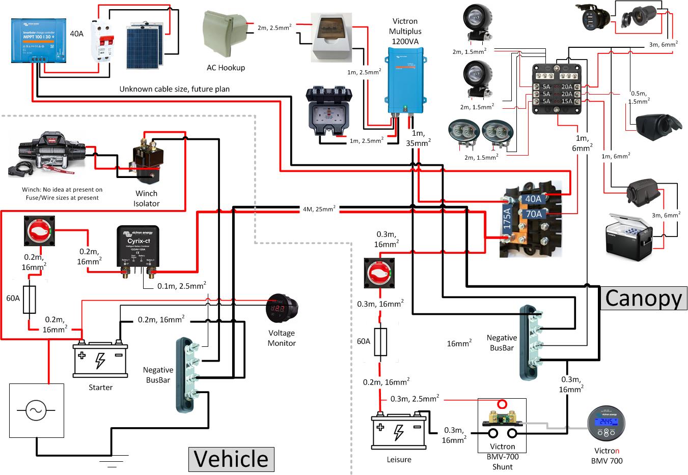
Draft 1:
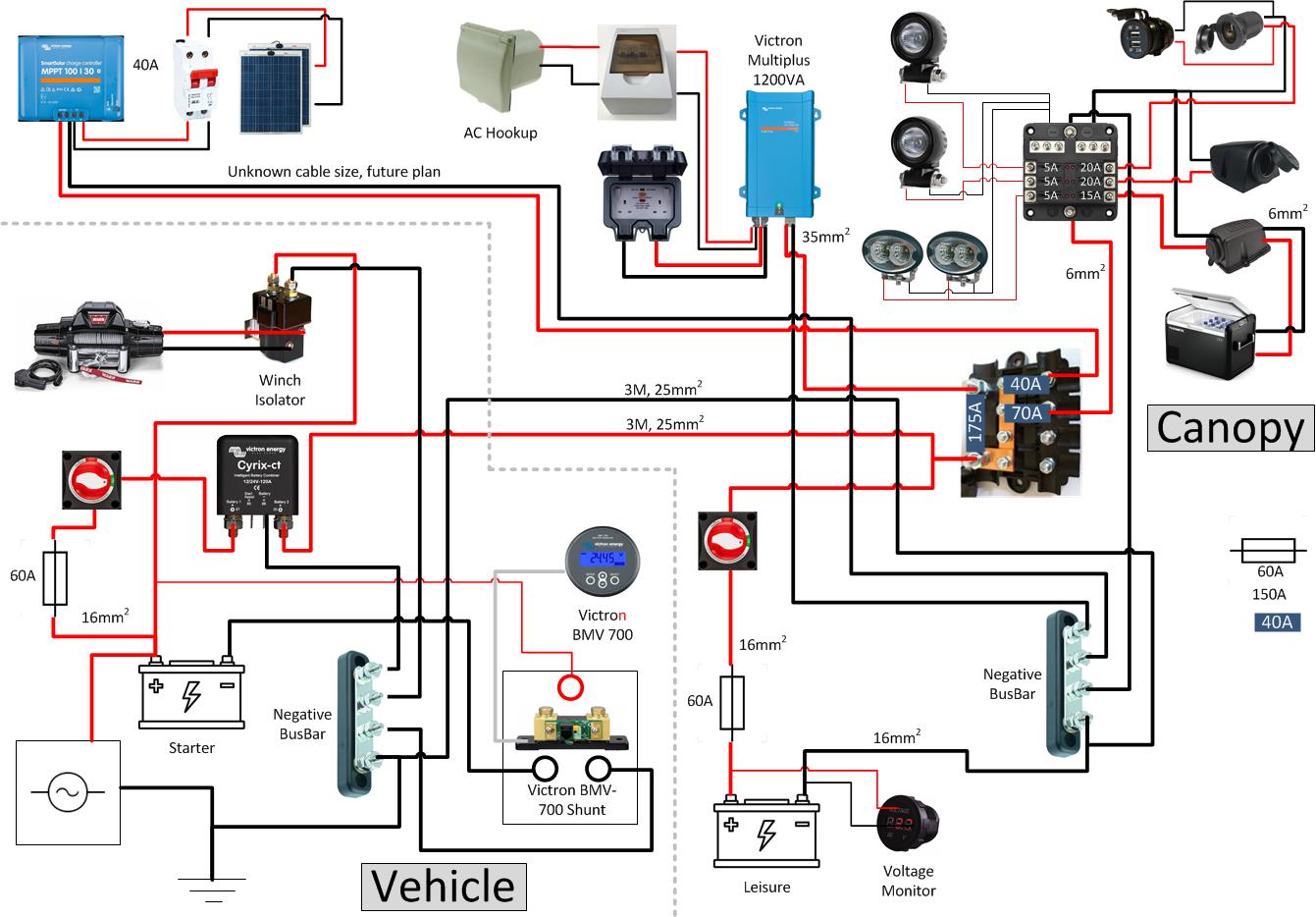
Draft 2: