I bought 700 watts of solar to go along with the 100-30 amp charge controller and I have only seen the highest watts of 150 coming from the controller. I even got it replaced and i’m still seeing such low numbers when the panels are in direct sunlight. I also tested the panels individually and they are both working properly
asked
Getting very low watts from charge controller
What is the battery voltage when you see 150W?
38.09V coming from the charge controller and on the victron 712 battery monitor it said 11.8 volts. I hooked up a shore power as well to charge the batteries and i’ve seen them go up to like 14.4 (Victron AGM batteries, I have (2) 200ah batteries.
By 38.09V, I assume that's the panel voltage, so that's coming IN to the charge controller, and you're saying the BMV is reporting 11.8V when you're only getting 150W?
First, with a 100/30, you're never going to get more than 440W, and that's at 14.7V battery. Below 14.7V battery, you'll get less. At 11.8V, you'll get 11.8*30 = 354W maximum.
I would confirm that 11.8V with a voltmeter. 11.8V is WAY too low for AGM, and you may be damaging your batteries if it's truly that low.
While your panels may "be in full sun," not all full sun is the same. Right now, if you're in the Northern hemisphere, your panels may never harvest more than 50% of their rated power, and it could be worse depending on orientation and tilt.
When the BMV reports 11.8V, what is the battery %?
What is your latitude?
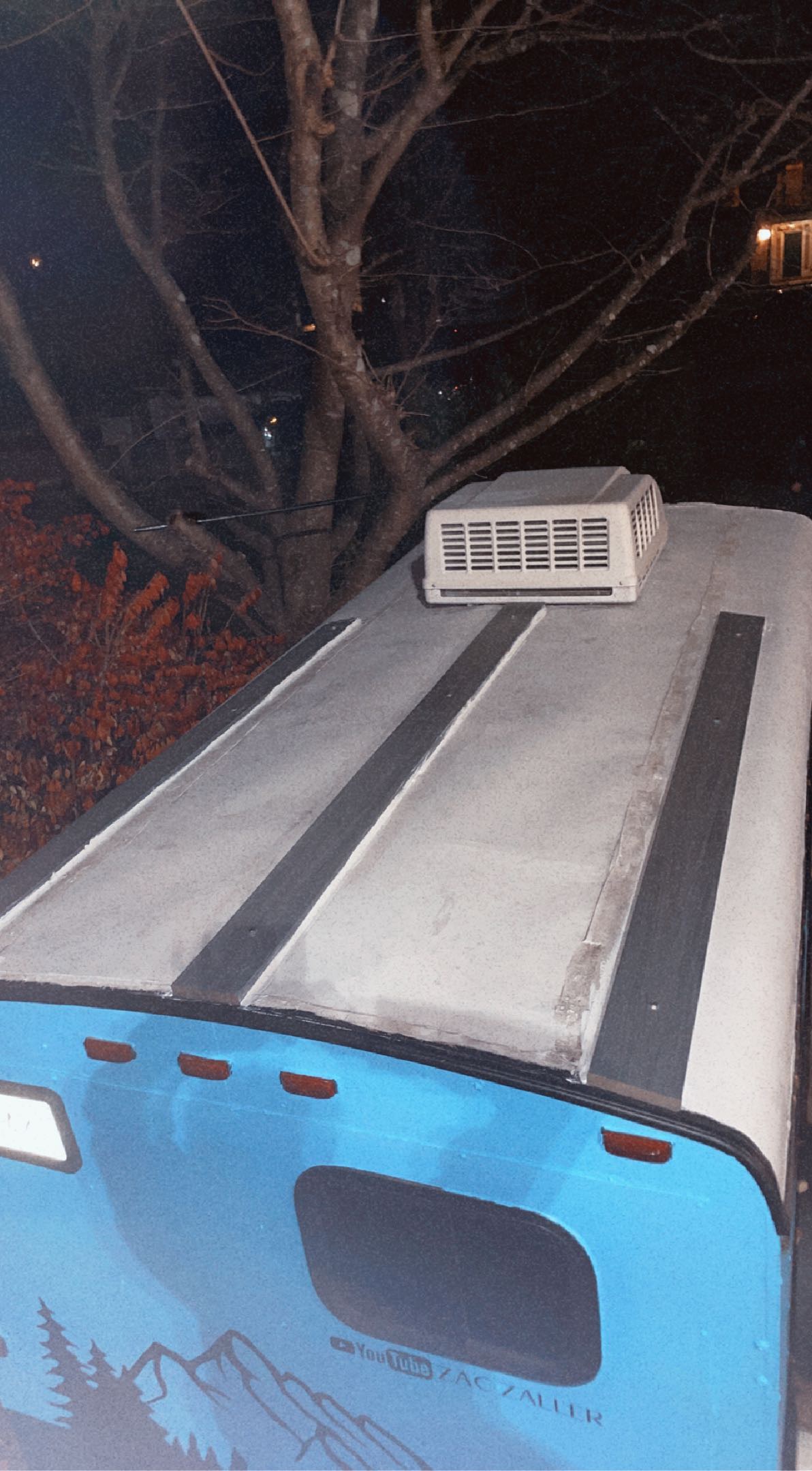
How are the panels mounted?
How are the panels wired?
How did the Isc compare to rated when you tested the panels?
My gut says that you're likely over-utilizing your available solar and continually draining your battery. If you continue this trend, you're going to destroy the batteries.
Yes the BMV reported 11.8V today and I was still only getting 150W of solar.
So if your saying with a 100/30 I will never get more than 440W. What charge controller would you recommend I buy for 700 watts of solar? I can also confirm the voltage on the batteries but i’m pretty sure they got that low because I have barely gotten any watts from the sun to charge the batteries and a mini fridge has been running consistently. I currently have it hooked up to shore power to get those batteries back to full capacity since the sun isn’t doing it. I am currently in maryland so that makes sense why they won’t harvest more than 50%. So basically in order to get the battery % you have to synchronize to 100 and i was told to hit that button once you see the float light go on. I’ve never seen that float light go on at all but i hit synchronize when the battery voltage said 14.4, with that in mind, the battery percent said 88% when the voltage was at 11.8V which i know is incorrect. I don’t know how to get my battery percent to be accurate. The two panels are mounted on the roof of my trailer long ways with one slightly tilted to the right and the other to the left. I’ll add a picture. the two panels are wired together with Y branch connectors which then goes down into my trailer and to the charge controller. Once again let me know what I should buy to get the 700 watts of solar i have available. I’m not sure what the lsc means but when i tested the panels the rated was around 39V-45V and each panel said 42V
 setup
setupMPPT 100/30 means 100Voc maximum and 30A CHARGING maximum.
700W/12V = 58A
It would probably be best to get a second 100/30 and attach one panel to each. HOWEVER, the MPPT is not what's limiting you at this time. It's the sun in the south and partial shading, so you're not ready for another MPPT yet.
Isc is one of the parameters on the back of the panel. It stands for short circuit current. It's the only way you can get some indication of the panel's potential in any given condition. If the Isc = 10A, but you measure 5A, the panel is only capable of meeting about 50% of the rated power. This is likely due to the solar energy hitting the panel being reduced.
You measured the Voc (Voltage, open circuit).
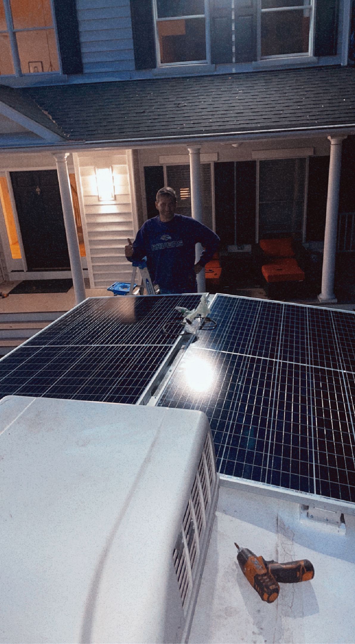
That A/C unit can also have devastating effects even if it's just partially shading the portion of the panels closest to it. Those look like bifacial panels, so the half farthest away would be unaffected, but the halves closest would experience substantial performance hits.
This has crappy audio, but it gives a good visual demonstration of how partial shading can really impact production:
https://www.youtube.com/watch?v=DbqY-HBPFTU
Generally don't force a BMV to 100% unless you KNOW it's 100%. It's important to make sure the BMV is properly configured. Take snapshots of the BMV Victron Connect configuration and post here. It is important that the battery be fully charged at least a couple times a month to ensure it's accurate.
I assume you're using the AIMS as a charger from shore power. They tend to have a VERY long absorption period (where voltage is held at peak) - absurdly long in many cases. If you notice that it's been at 14.4V for more than a few hours, and the current reported by the BMV is less than 12A into the battery, then it's done, and you can terminate shore charging and synch the BMV to 100%.
Again, your problem right now is NOT the MPPT. You can spend money on a second MPPT, and you won't get any additional power if there's not enough sun hitting the panels.
Your minifridge likely uses a lot more power than you might suspect - probably less than 5 days to completely tap out your battery.
You should avoid discharging your battery by more than 50%. If your battery voltage ever hits 12.0V, terminate all loads/charging by turning the master switch off so you know it's isolated. Let the battery sit for about 30 minutes. The voltage will rise. After 30 minutes, compare the voltage to this chart:

That will give you a good sanity check on the BMV accuracy.
AGM batteries degrade any time they are not at 100%, so every reasonable chance you get to take them to 100%, you should take it.
Lastly, try parking the rear of your RV due South with no shading. At noon, turn on several loads to make sure you're using more than the solar can deliver (no shore power either). Check the solar output - that will be your maximum available for this time of year for your panel's orientation. Important to use loads because if the batteries are full, they will not accept the max power available - only what is needed to hold at absorption or float.
Thank you so much. That was so much information but it was exactly what I needed. In general you explained that my MPPT can only take up to 440 Watts so i’m returning it and i ordered the 150v/70amp victron smart charge controller to replace what I currently have.
That aside, I understand the partial shading completely so when I park I always make sure the sun is behind the trailer so the AC is not in the way.
I have also attatched here the panel rating that I got from Santan Solar’s website for the panel I bought
I will get back to you in the next few days when I setup the new MPPT and go test it at noon like you explained. I also will send you pictures of my settings for the MPPT and the battery monitor cause those my be incorrect as well.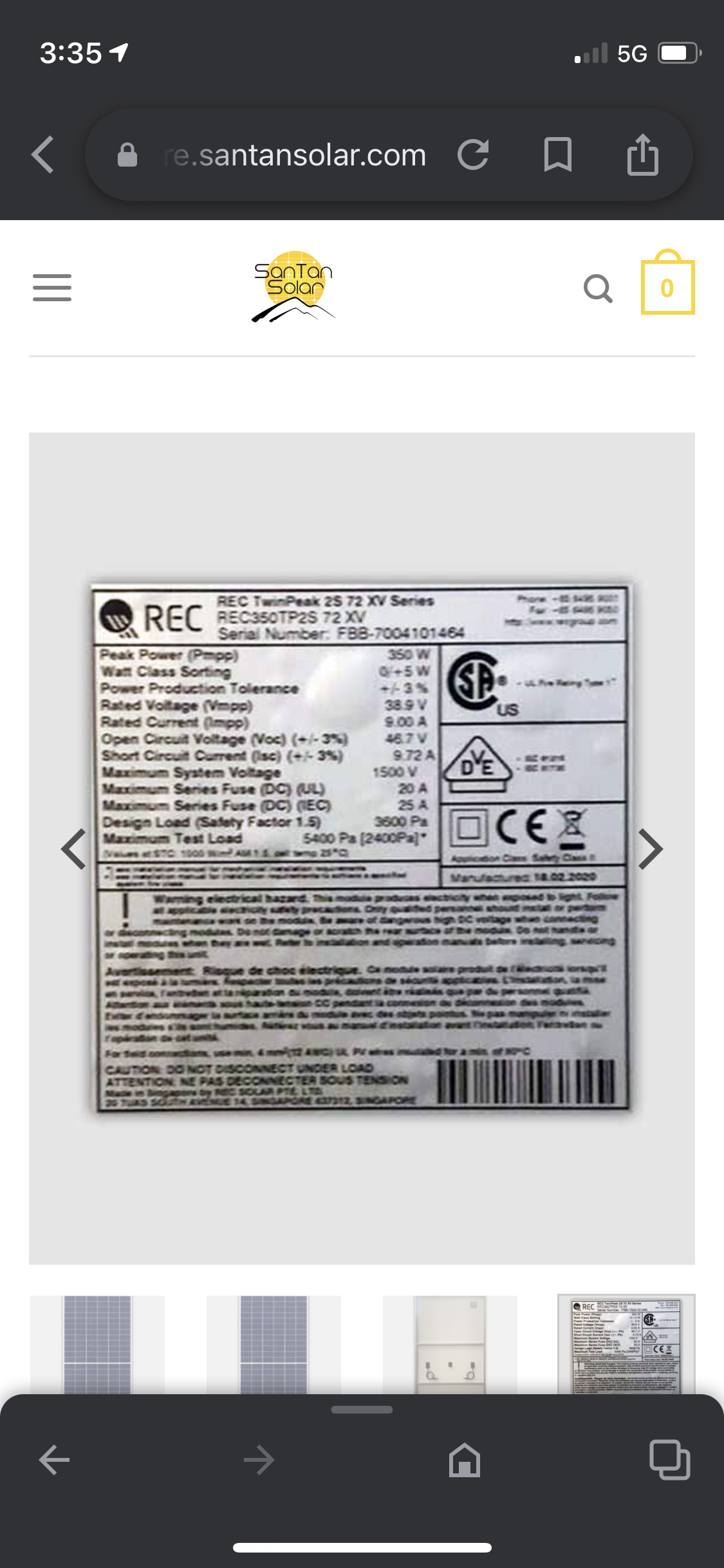
Again, I want to reiterate that the 150/70 will not improve your situation at all. The panels currently can't deliver anywhere near 30A of charging current. It will likely only help significantly in the summer months.
Panel info:
Isc = 9.72A.
Check each panel's current individually:
https://www.youtube.com/watch?v=eh6hzMb69gY
@zaczaller to give you an idea of how far solar output drops, my system, which in summer delivers over 500W is barely doing 10W on a poor winter day in the south of Germany.
Solar panels generate a high voltage in winter, even with weak sun. But as soon as any load is put on them, the voltage drops fast. MPPT controllers keep the panel voltage high, but with low current. Panel voltage is misleading, it often looks like there's a fault because voltage is high, but it's not. It's the solar controller doing its job of getting the max out of the panels by not allowing the voltage to drop too far.
so with that in mind… even with 700 watts of solar it’s unrealistic to get any real charge during the winter? I built this tiny house trailer to take with me to college to potentially replace getting an apartment. I thought I would have plenty of enough power with 700 watts of solar charging 400ah of AGM
Guessing not. Sorry. I put LPG heating in mine, not sure of there's enough solar to drive that. So am fitting a charger from the alternator.
Not during winter.
Here are insolation numbers for Hagerstown, MD:
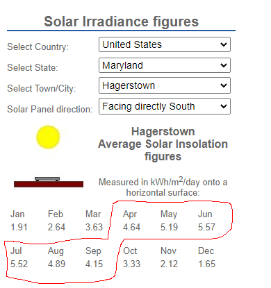
Note the above factors weather into it, so it's not just solar positioning. Apr-Sep are pretty good, even march and October are decent, but Dec and Jan are garbage.
5.57 in Jun means on average, you can collect 700W * 5.57h = 3899Wh of energy per day.
1.65 in Dec means on average, you can collect 700W * 1.65h = 1155Wh of energy per day.
BOTH scenarios assume that the panels are not shaded at all and receive solar exposure from sunrise to sunset.
Weather and shading will skew the results.
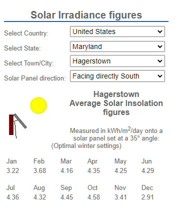
Once parked, if you could tilt them up 55° from horizontal facing South, your winter production would be notably improved:
My gut tells me that you didn't do any significant load analysis prior to embarking on the project, i.e., how many Wh you need per day. If you had been counting on solar for heating and cooling, 700W is not even remotely close.
If you can park somewhere and access AC power, then electric heating/cooling becomes viable, but you'll gobble power.
Thank you :), heating is actually off propane and cooling is not really necessary I just crack a window. The only things i’m running are lights and a mini fridge consistently and I believed that 700 watts and 400ah battery was enough to do that.
It is enough... 7 (probably half of Mar and Oct too, so 8) months out of the year or so.
Mini-fridge like a dorm fridge can use a surprising amount of energy, 1-1.5kWh/day.
Your inverter also has a very high idle burn rate. Those are not particularly efficient. They consume power just by being on. Assuming it's a 4kW unit, it probably AT LEAST 42W with no loads attached - 42W * 24h = 1008Wh.
Let's say the fridge uses 1kWh/day. On top of the idle burn, the inverter is only about 80% efficient at low power levels (if you're lucky).
So, that 1kWh/day consumes 1/0.8 = 1.25kWh of battery capacity.
1.25kW fridge + 1.0kW inverter = 2.25kWh/day
2250Wh/day / 700W = 3.2hrs, so any month on that chart with less than 3.2 hours will fail to provide the needed daily energy to run the inverter and fridge alone.
Something to consider... for your small loads, a 500W-ish PSW inverter will have a much lower idle burn and can power the small items with less self-consumption and likely higher efficiency. I would confirm a 500W could handle the fridge compressor start-up if you go that route.
400Ah * 12V = 4800Wh, but you should only use half of it without damaging the battery. In that case, it's 2400Wh - about 1 days worth of inverter/fridge.
Time to move forward. You have some options:
Mains charge
Alternator charger
Standalone generator/charger.
Might be others, but I cannot think of one.
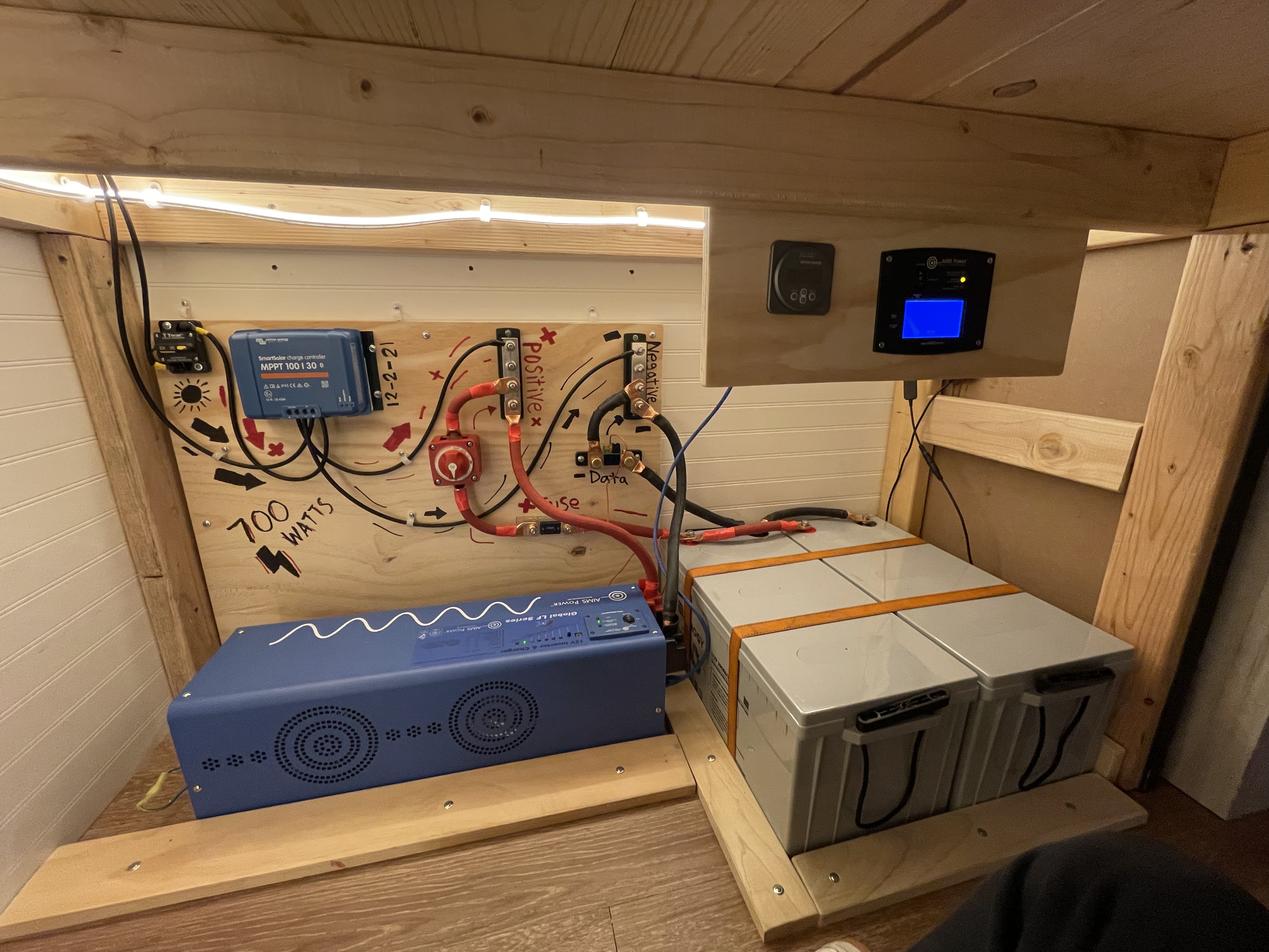
My solar charge controller is showing float and that my lithium 300ah battery is at 14.6 volts but my victron 712 battery monitor is showing 13.14 volts. I just setup this entire system and I’m not sure why the charge controller is entering this float when the battery is not fully charged.
That sounds like you have voltage drop, do you have a multimeter to check the voltages at both the controller terminals and the battery terminals. Measured with a single device should sort out where the error lies. Have you made your connections in the controller properly so that they have no voltage drop, are your cables the right size, do you have a fuse or switch in between the controller and batteries. Lots of cases of people here with nasty isolation switches that have a high resistance. What happens to the voltage discrepancy at night when there is no solar charge. If the controller and BMV712 agree with no current flow, but show a discrepancy when current is flowing then definitely a high resistance. When current is flowing you can measure voltage drop over any switches, or fuses or from controller +ve to battery +ve and controller -ve and battery -ve to try and identify where the voltage drop is occurring.
Tell us a bit more about your set up and try to get some voltage measurements.
 here is the setup. i’m sure all of the cables are the right size.how do i test these voltages. do i have to take the battery cables apart and also how do i check the voltage on the charge controller?
I assume you have a digital volt meter and know how to use it, this really is the basics. On the controller you have the 2 screw terminals for + and - going to the batteries. Use the voltmeter to measure the voltage here. Then measure at the busbars. Then measure at the battery. Do this when the controller is charging and when it is not charging. They should all be the same when not charging and within a few fractions of a volt when charging. They can also be compared with the controller and the monitor. If they are 1.5V different as your numbers above, then you can see if the difference is between the controller and busbars or busbars and battery. If you set the voltmeter to a low range like 2V, tjen you can put one probe on the controller + terminal and one on the + busbar, the difference should be vert small, if it is 1.5V then that cable or the terminal or the screw connection have a high resistance. You for this for each section of cable, switch and fuse until you find the missing Volts.
Your photo does not show any fuses or switches in the solar cable as far as i can see so no sources of voltage drop there. Victron recommended a fuse in the cable from the controller to the battery, you need something to protect that cable from a short.
Sounds good I can do this, i appreciate the instructions. I do have a 300amp fuse from the positive bus bar to the positive end of the battery it’s just hard to see on the picture. I will get back to you soon
Also. Is it okay that the wire from my bus bar to the batteries and the bus bar to my 2000 watt inverter be 4/0 gauge wire. could that be restricting it? All of the other wire between the solar and the controller and the controller to the bus bars are using 10 gauge wire. Lastly I did add a battle born 12volt battery heating pad straight to the positive and negative bus bars. It goes from the bus bar to a thermometer and then the heating pad so it only turns on when the meter reads below freezing. Could any of this be the reason my charge controller is showing much higher voltage then my battery monitor?
Your solar cable seems a bit thin for potentially 60A current if your panels deliver peak power but for your low amps at the moment they are not too bad, but still higher voltage drop than desired, but not 1.5V. However having said that, the high resistance if there is one could be in any of your bolted connections or crimped terminals. Your terminals looked like copper, i normally expect to see tinned connector to avoid tarnishing of the copper.
Please make a screenshot of the history tab.
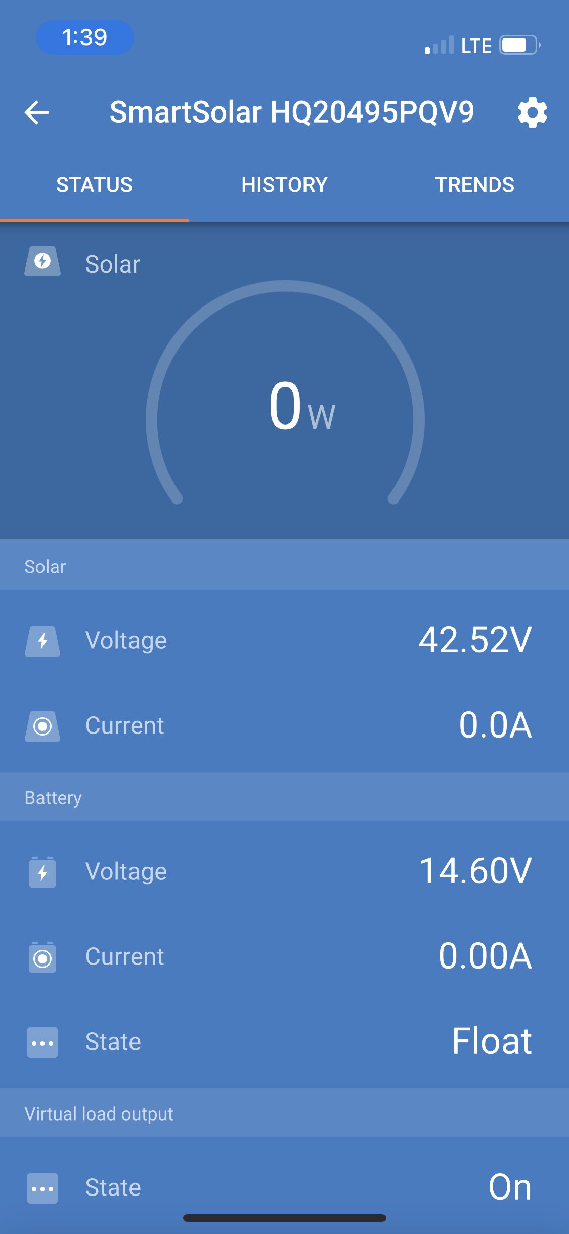
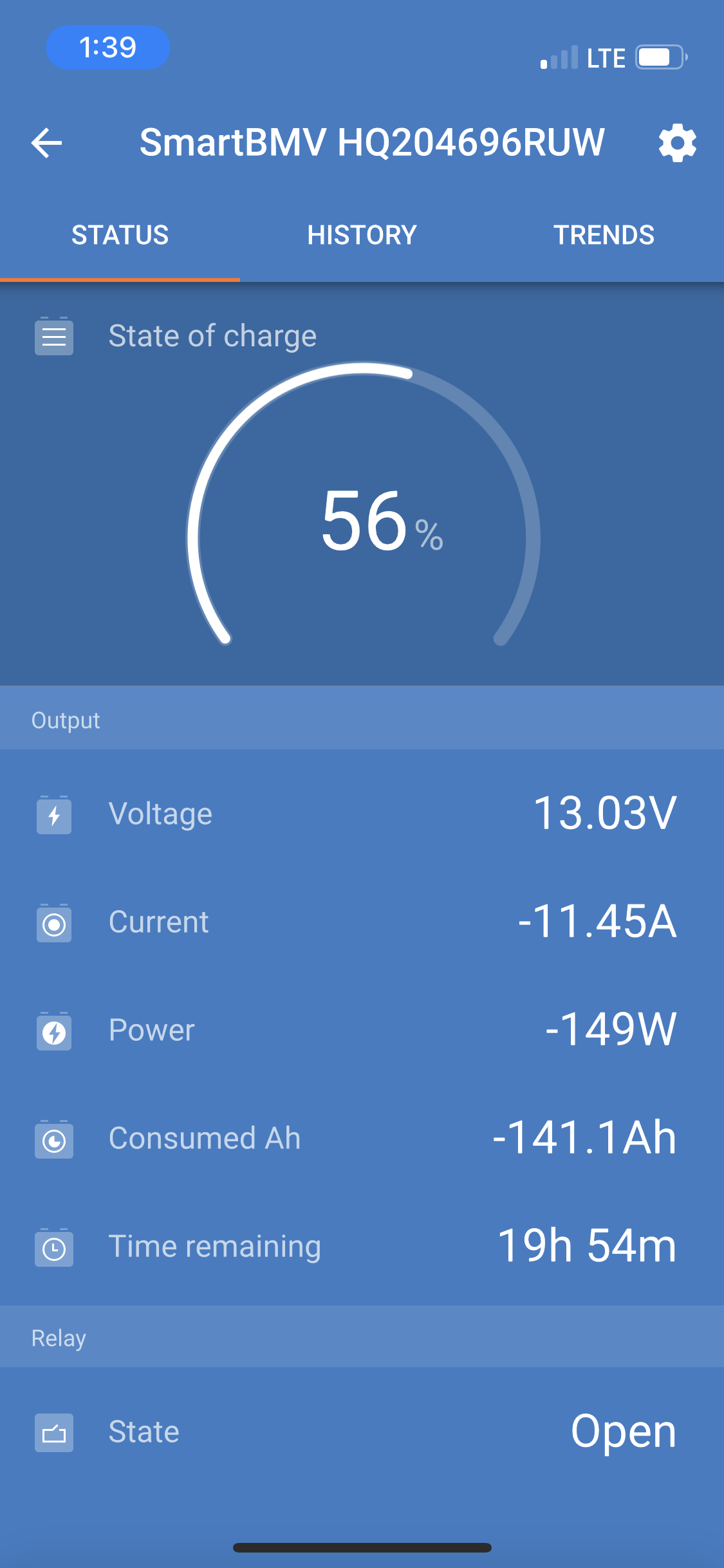
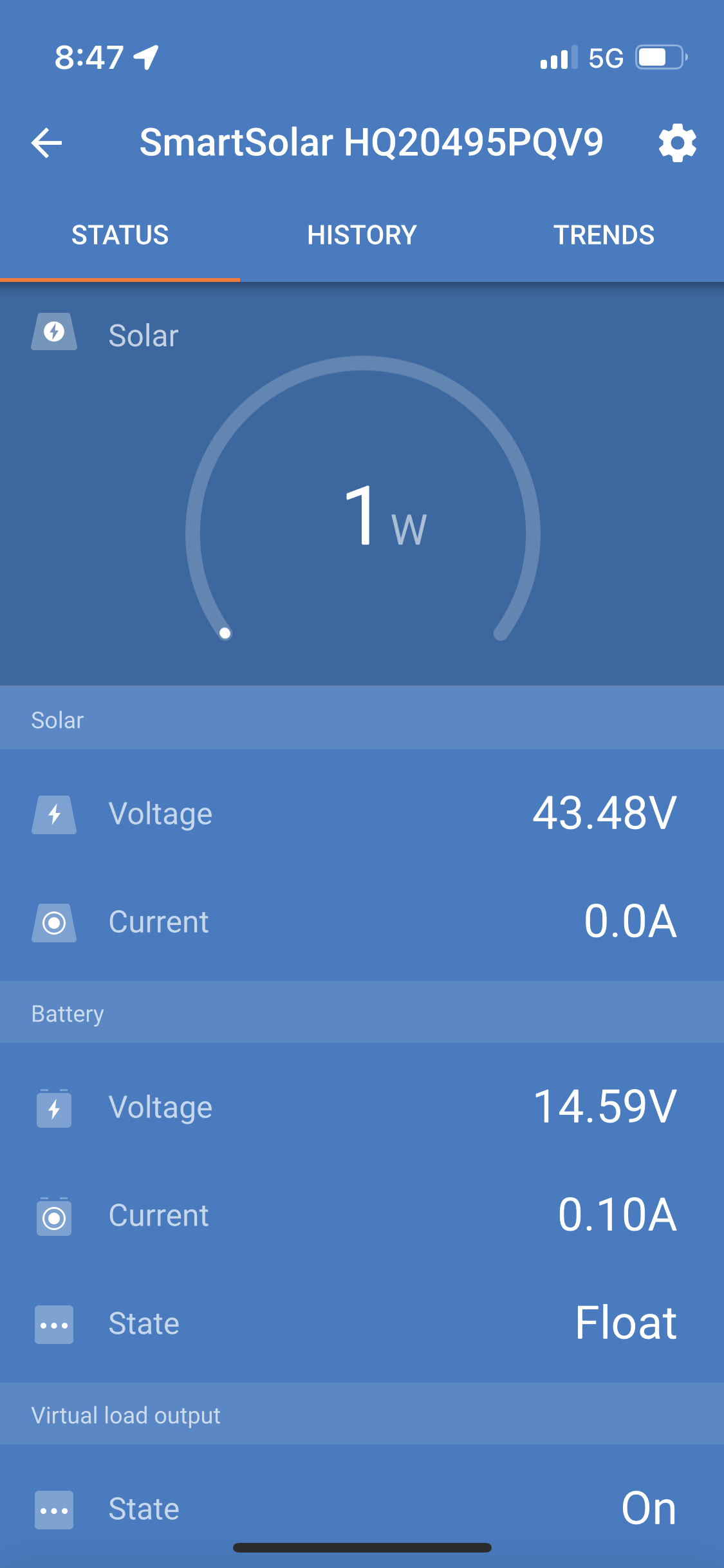
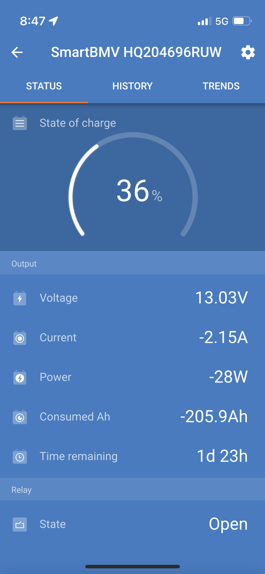
14,6V and 0A at the MPPT and 13V at the BMV looks like there is no connection from the battery to the MPPT.
Try to disconnect the PV from the MPPT and look what happens. I guess the MPPT will shut down because it don't have a connection to the battery.
Also measure the voltage at the battery terminals of the MPPT.
If you measure the correct battery voltage there (13V) the MPPT is defective because an internal fuse is blown.
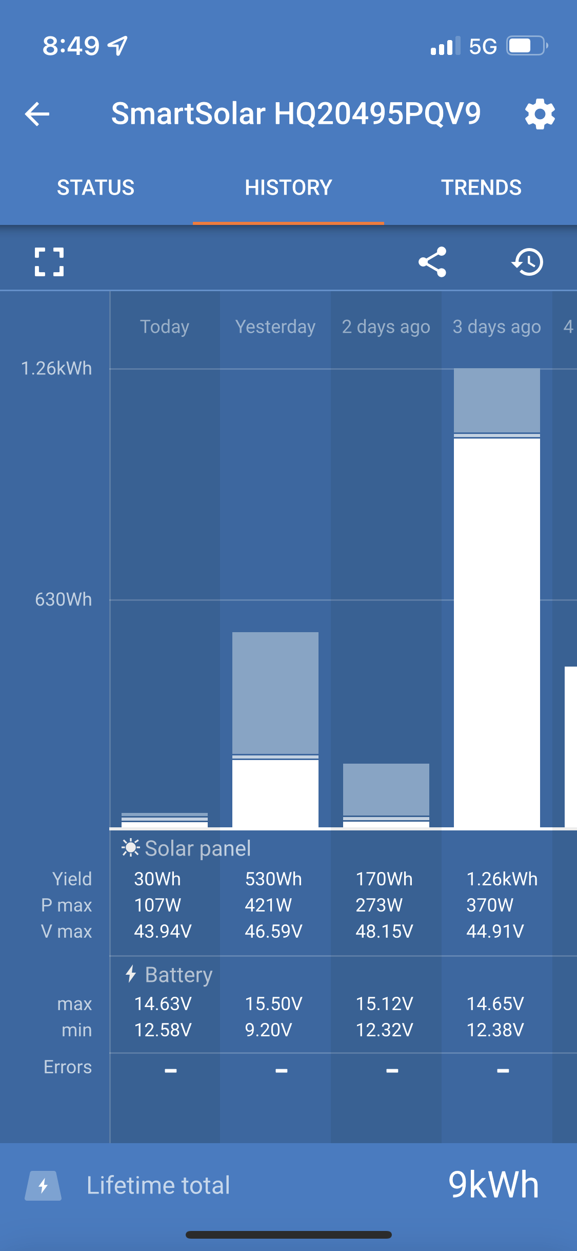 BAA7A5F8-85C7-4AF1-AED8-4603C3DD54BD.pngAll three screenshots are from this morning with the sun jus coming up. Last night the voltages read practically the same on both MPPT and Battery monitor but as soon as the sun rose the mppt went on bulk for a second and suddenly said my battery voltage was at 14.6 and hit float when clearly on the battery monitor it’s no where near charged. I am feeling a little hopeless as to what to do because I’ve followed the entire build process correctly and can’t figure out why this won’t charge my lithium battery properly.
Have you had any luck fixing the problem where voltage on the SmartSolar has 43 volts but only 1 watt. I have the same issue after doubling the wattage to 800 wats by doubling the number of panels on my roof. In my case it's stuck on Bulk but it's not charging the battery at all. It worked perfectly for over a year before changing.
I think the lead from the panels to the MPPT 100/50 is now possibly too thin.
Should i take apart the 4/0 gauge wires and replace them with 2 gauge wire instead?
No, the 10 gauge from controller to bus bars is on the thin side, my 700W solar with 150/60 controller has closer to 6 gauge wires, I am metric so 16mm2 conductor. The controller to busbar needs to be much larger than panels to controller as the amps is higher. The 4/0 wire from busbars to battery and inverter looks OK.