Placing a shunt to monitor current in the negative lead is not always possible. To monitor a battery, it really does not matter if the shunt is placed in the positive or negative lead. But as shunts take on a more general metering role, finding a place to break the negative connection isn't as easy. For example, monitoring the current from an alternator that makes it's negative connection to the engine block makes a shunt in the negative lead impossible. DC-DC converters/chargers that don't have separate negative connections (non-isolated) are another example of where a shunt must be in the positive lead. Many times, loads are returned to the vehicle chassis rather than a separate wire to the negative side of the battery. This is another example where the shunt must be in the positive connection to that load.
- Home
- Anonymous
- Sign in
- Create
- Spaces
- Grafana
- Node-Red
- Unsupported topics
- Questions & Answers
- Modifications
- Communauté francophone
- Deutschsprachiger Bereich
- Preguntas en Español
- Explore
- Topics
- Questions
- Ideas
- Articles
- Badges
Idea
I’m also after this. I have a number of RF equipment items that have their DC Negative and RF ground linked on a chassis level in a rack, which are in turn linked by the fact they’re bolted together.
Even if they weren’t bolted together, the antennas mounted externally have to be connected to a common ground for lightning protection. This creates some interesting current sharing over the negative paths if trying to measure currents on individual devices.
in this instance, a negative shunt is still possible, the battery negative becomes an active connection, with the true ground on the load side of the shunt.
The alternator issue is the true problem with chassis return. This does need the option of a positive side shunt.
It's pretty rare that you can't get away with a negative shunt. You just need to think the circuit through in terms of Kirchoff's Voltage and Kirchoff's Circuit Laws. My alternator is monitored by a shunt between the engine ground and my DC ground, but that's fine because the only current that will be flowing form the positive terminal of the alternator is going back to my lithium battery. The engine starter current, and output of the (isolated) DC:DC charger are on a circuit with their own flooded lead acid, and there's no way for that current to flow over the negative between the engine and the lithium battery, as they're connected at a single point.
No problem having shunts on the positive side (I made 2 of them with 300A shunts and INA226 boards for data acquisition)
The only problem is, you need fused probe wires for safety when you are on the high side.
This is OK if you have the capacity to interface to the I2C bus (this would allow for several shunts in one application). However for those without this ability, there are very few comecial shunts with positive bar capability. Also, if the boards are close to the shunt, fuses may not be necesary, but some series resistors in the sense lines would be needed to protect the ground and data lines.
Yes, but easier as you think, I use an ESP32 as controller, it has I2C ports and I use WiFi to transfer the data to the VenusOS via UDP. Wireless shunts are great, you can place them at quite a distance without additional wiring to the main unit, you can monitor them remotely and they are very accurate and resilient to magnetic fields nearby in contrast to HAL sensors.
Yes there is a problem, which is buying the damn INA226 in the first place. These things are affected by the chip shortage. Farnell list them as "expected August 2023".
@JohannDo This sounds like the exact solution I'm looking for to account for a non-isolated Orion with DVCC. I think I'd connect directly to the Pi's i2c bus and use pulquero's dbus-i2c service to publish it as a DC system device. I assume you used one of the premade boards, replaced the shunt resistor with an actual shunt and set the registers appropriately, but I'd appreciate any and all info you could share :)
You can do this, it is straight forward to programm the INA226.
You have to remove the shunt on the board if you wanr a different current range.
My approach is a little more complicated, as I built a wireless shunt controller, using 2 x INA226, 2 x 300A shunts, a ESP32, an OLED display and a buck converter to power the unit. It is 8m away from the RaspberryPi Venus and uses WiFi to connect to the Pi, data is published by UDP broadcasts and I wrote a python service to receive the data and publish it on the DBUS as 2 separate devices, so it can be logged in VRM. I also modified the overview page to get the data on the screen in Venus. It has ahttp server too, so internal statistics can be monitored, the device can be configured and firmwareupdates can be done OTA.
Quite happy with the solution.
why didnt you use ina3221 instead of 2 226s.? i was just searching for a good shunt to do the same and ended up here
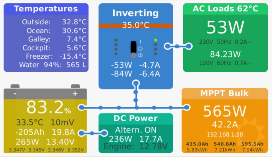 Venus OS Overview page modified
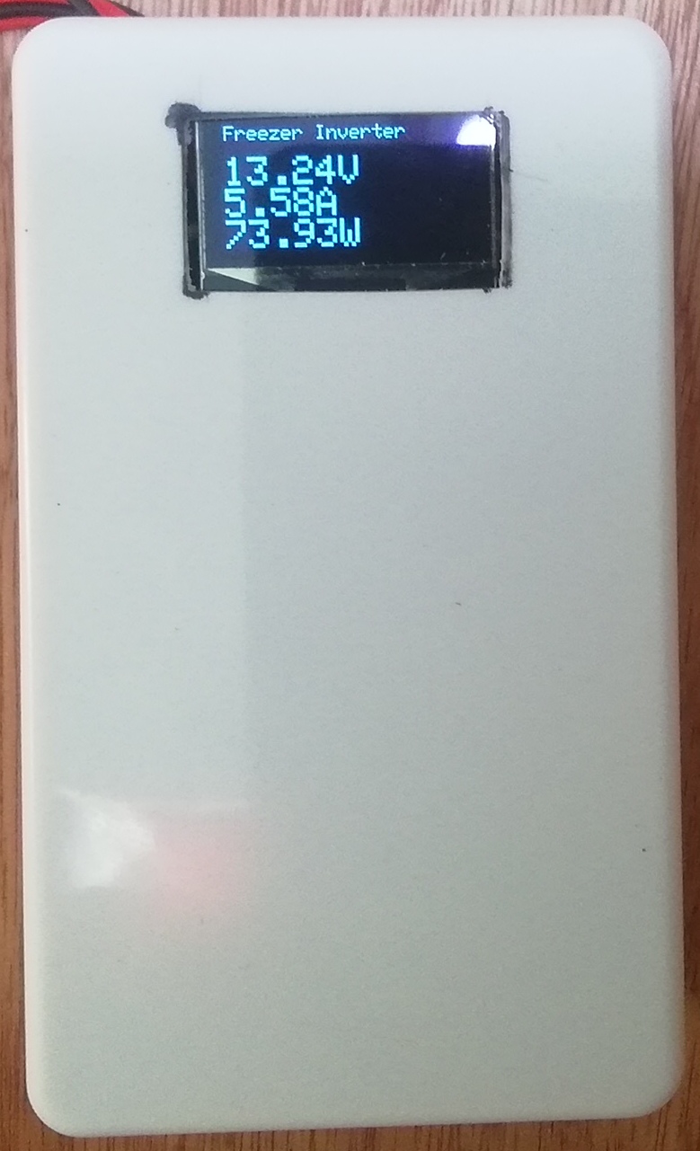 Wireless Shunt interface
img-20220715-101735.jpg
(225.4 KiB)
img-20220716-143801.jpg
(131.2 KiB)
Another option is to use a hall effect sensor instead. No shunt required.
Hello, any news here?
SmartShunt in positive wire as a DC meter should be so great.
Perfect with VE.Can or Bus to use several SmartShunts.
Best regards Robert
Your Opinion Counts
Share your great idea, or help out by voting for other people's ideas.
IDEA DETAILS
29 People are following this idea.
Related Ideas
BMV 7XX via VenusOS: SOC Reset & Relais Programming
Feature request for BMV-712 - Set SOC
Mod Battery Monitor Audible Alerts
Smart shunt with differents roles
Useability Modification to Trend Screen
Feature request: remote configure BMV/SOC sync
Charge Current Limiter including Alternator