question

Jim avatar image
Jim asked

VRM missing load - all inverter loss?

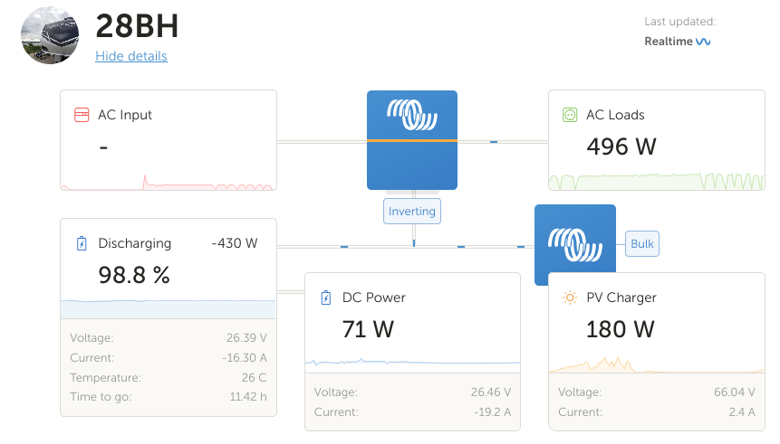
I have a DC solar setup with lithium batteries and a multiplus 3000/24. Everything is working well, but when looking at VRM, part of the load is missing. That is, the numbers do not add up. My AC load is primarily resistive, with a gas absorption fridge utilizing heating elements, the wiring is proper or oversized, and the load is low enough that wiring loss is negligible. Inverter efficiency, power factor of other small loads, and charging losses might make up the difference, but it would be really nice if the VRM portal numbers came closer to adding up. It would also be nice if the Multiplus could report power factor of the AC load. These things aside, though, am I missing something on why the load numbers are so far off? 100w on a 600w load seems significant. Thanks for any insight.

1626787901185.png

Jim


Multiplus-IIMPPT ControllersVRM
1626787901185.png (79.2 KiB)
2 |3000

Up to 8 attachments (including images) can be used with a maximum of 190.8 MiB each and 286.6 MiB total.

5 Answers
marekp avatar image
marekp answered ·

Efficiency of the inverting at that power level is circa 90% (power used by MP itself and GX device do lower the eff.)

430 x 0.90 +180 - 496 - 71 = 0

I do not see anything wrong with your numbers.

1 comment
2 |3000

Up to 8 attachments (including images) can be used with a maximum of 190.8 MiB each and 286.6 MiB total.

Jim avatar image Jim commented ·

The numbers make sense. It would be nice to have them all displayed in VRM to give a net 0. Alternately, an inverter efficiency number could tell the story too. Thanks for the replies.


0 Likes 0 ·
Alexandra avatar image
Alexandra answered ·

@Jim

Did you also consider the power the system takes to run itself?

I have found with pv invters and mppts and gx devices people often forget they use power as well. Can be 100W on smaller systems, on larger 3 phase systems even more.

2 |3000

Up to 8 attachments (including images) can be used with a maximum of 190.8 MiB each and 286.6 MiB total.

Jim avatar image
Jim answered ·

Hi @Alexandra , thank you for the reply.

I did consider those loads, and they should show up in the DC load box as the power they pull would come from either the solar or battery, but either way across the shunt (BMV-712). There is 71w of DC load accounted for, which seems about right given things running on 12v DC, including the Cerbo, MPPT, WiFi, and some other parasitic DC loads.

Solar production + battery = all incoming wattage to the system. From the picture, 430w from battery and 180w from solar = 610w.

Displayed load would be DC Power + AC load = 565w

For this image, the delta then is 45w. It would still be nice to see the 45w called out in VRM as "system loss" or such to make the picture complete.

1 comment
2 |3000

Up to 8 attachments (including images) can be used with a maximum of 190.8 MiB each and 286.6 MiB total.

Alexandra avatar image Alexandra ♦ commented ·
@Jim

MarekP Is right on the money there. Efficiency is also important, and I have seen systems with much larger "losses" than yours. Your figures look good.

0 Likes 0 ·
xenofon-issaris avatar image
xenofon-issaris answered ·

It is the same question I wanted to make so I put it here. my VRM shows this loss. At 12 o clock today it was even worse, showing at 3100 W solar and 2600W loads almost -1000w. The temp outside is 42 degrees and at the little room where the inverter is not less cause is an external room no AC. Can it be the heat?
1721311220084.png


1721311220084.png (150.3 KiB)
3 comments
2 |3000

Up to 8 attachments (including images) can be used with a maximum of 190.8 MiB each and 286.6 MiB total.

nickdb avatar image nickdb ♦♦ commented ·

This image is losing 397W from 2525W DC, which is 15% well within a 10 to 20% typical range, depending on the type of load it is running (some are more efficient than others).

Of that, depending on what the system is, probably near 100W is being used to power the devices themselves, something which becomes insignificant at larger loads, but is disproportionate at lower loads.

Running a system at 42C is a bad idea, you will be seriously degrading your battery life and reducing efficiency and performance, which is based on 25C. I would get cooling into that room.

0 Likes 0 ·
xenofon-issaris avatar image xenofon-issaris nickdb ♦♦ commented ·

It is another time not at peak loss. Shows 2128(loads)-1360(solar) should be 768 decharge. Instead of that i have 1165 decharging which means 1168-768=400. At 3100 solar with 2800 ac loads I have almsost 400 decharge which is 300+400=700 loss. I have the batteries inside the house at max 30 C. The inverter and the solar chargers are at the little room right out the wall not to deliver all their heat inside the house.

0 Likes 0 ·
JohnC avatar image JohnC ♦ xenofon-issaris commented ·

@Xenofon Issaris

It's very easy to take a single screenshot and capture an imbalance. The reason is very slightly different sampling times of the values. You can actually enable the 'Has DC System' selection to quantify that imbalance in a 'DC Power' tile, it calculates it by difference. A lot of modern AC kit chops the sinewave faster than the sampling time can follow, and sometimes you can even perceive trends which don't exist. I'd expect poor power factor loads to impact too.

You can graph it as well..1721364997878.png
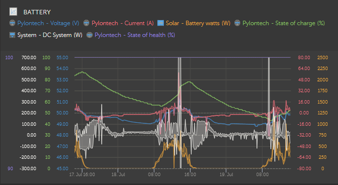
See the white line. I've enabled the range option, to show the variation which could have been reported. The white blobs are probably caused by a heater fan. The spike in the centre from an actual DC Load, so ignore that. The spike on the right though has caught me boiling the water jug and peaks at 1575W.

What you see isn't unusual. Just try to understand it a little.

0 Likes 0 ·
1721364997878.png (95.8 KiB)
xenofon-issaris avatar image
xenofon-issaris answered ·

Just now, 9 am, with 32 C temperature almost no loss at all

1721368732951.png


1721368732951.png (146.9 KiB)
2 |3000

Up to 8 attachments (including images) can be used with a maximum of 190.8 MiB each and 286.6 MiB total.