question

bmac avatar image
bmac asked

VRM at times missing power consumption for when bilge pump runs

  • Running 12V bilge pump (integrated float switch) connected to load output of SmartSolar 100/20 in a small well. Pump specs advise will run around 38W or thereabouts.
  • WEMA level sensor connected to Tank Input on Cerbo GX (set to 2 seconds reading averaging)
  • Battery is Pylontech RV100 12V
  • Other hardware is 12V router with advised consumption <6.5W


Using VRM (with data read every minute) to remotely monitor installation. Logic was to have 2 independent measurements to confirm things are working OK :

  • the changing sensor resistance from the level sensor
  • the power consumed when the pump runs


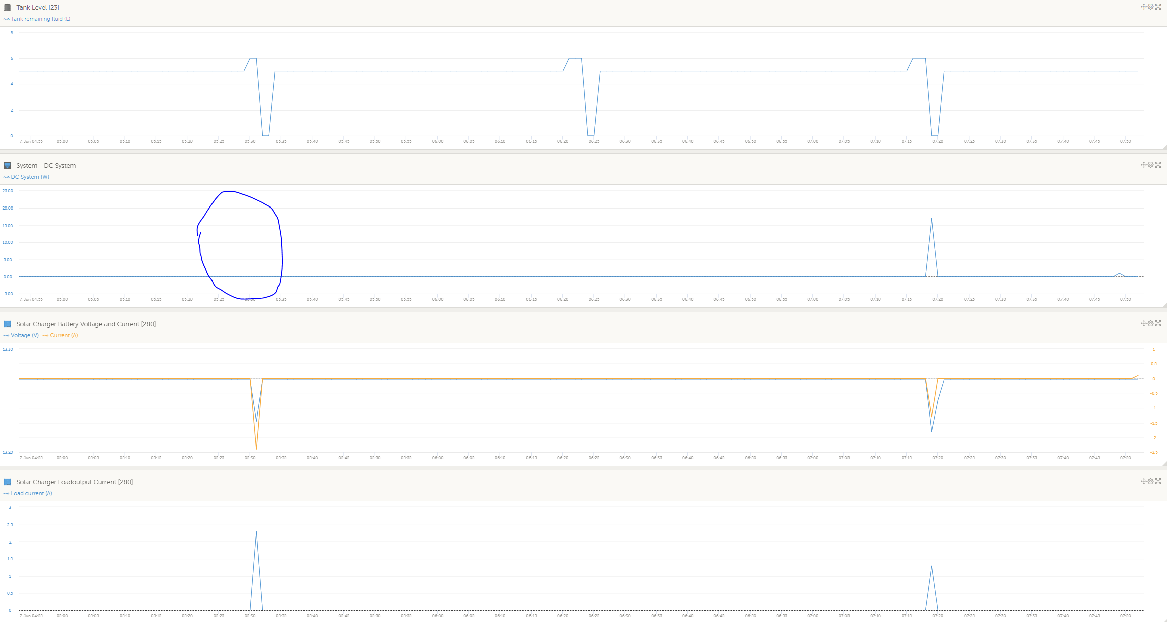
However, the consumption data is often missing as per this image:

1686042331184.png


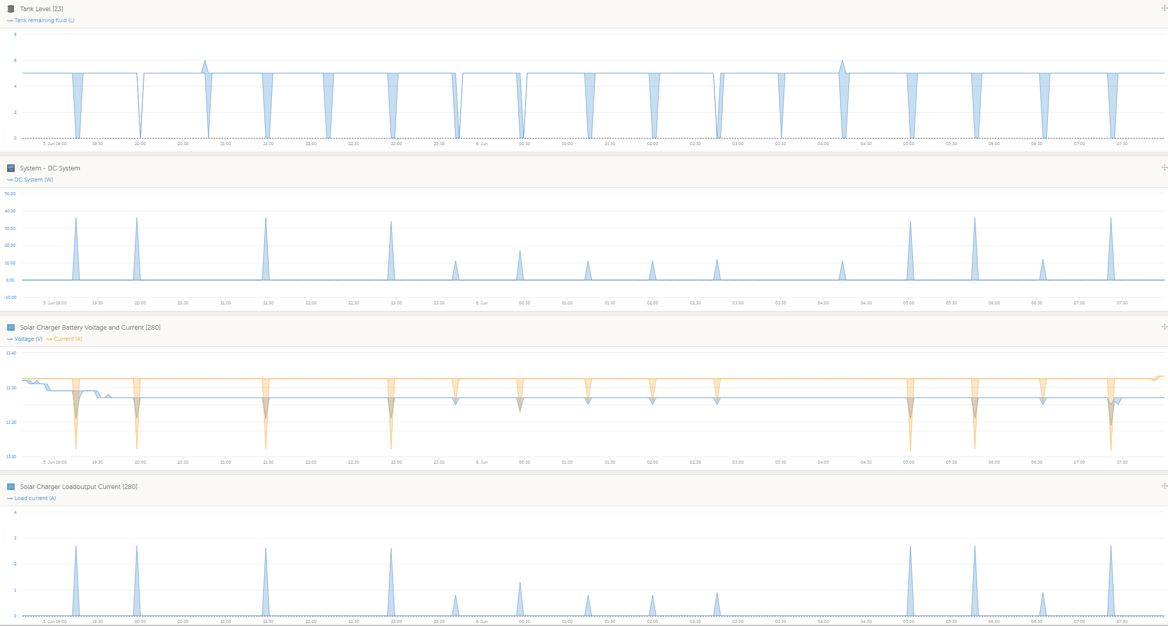
I assumed as the pump is running directly from the SmartSolar 100/20 it would capture the consumption - doesn't have to be 100% accurate but to be completely missing has me puzzled.


The pump will run for around 45 seconds when it cycles so maybe it is falling between the 1 minute reading gaps which i still don't understand why being connected directly to the MPPT, if that is the issue then how do i confirm via the VRM the pump has run?


Thanks.


VRM
1686042331184.png (145.6 KiB)
2 |3000

Up to 8 attachments (including images) can be used with a maximum of 190.8 MiB each and 286.6 MiB total.

3 Answers
bmac avatar image
bmac answered ·

These are the graphs from this morning. It shows the load was captured by the MPPT but not showing as part of the DC System graph. This probably throws out the theory of the pump running in between the times the data point is captured being the cause.


1686088713929.png


1686088713929.png (96.8 KiB)
1 comment
2 |3000

Up to 8 attachments (including images) can be used with a maximum of 190.8 MiB each and 286.6 MiB total.

bmac avatar image bmac commented ·

Bump

0 Likes 0 ·
nesswill avatar image
nesswill answered ·

Sample time causing it to miss the event?

I have seen something similar so i watched (at the time it happened) and that is what it was for me.

2 |3000

Up to 8 attachments (including images) can be used with a maximum of 190.8 MiB each and 286.6 MiB total.

pwfarnell avatar image
pwfarnell answered ·

The DC system current is a calculated value which compares the battery shunt current and the solar controller current and any difference is the DC loads. Sometimes this does not match reality because the battery shunt and solar controller have different sampling frequency. I do not know how it handles solar controller load current. The other thing is it does need a battery shunt / current measure either from the battery BMS or from a BMV or SmartShunt. I do not believe your battery communicates with the Cerbo and you do not list a shunt.

2 |3000

Up to 8 attachments (including images) can be used with a maximum of 190.8 MiB each and 286.6 MiB total.