question

ssybert avatar image
ssybert asked

Multiplus design review - pseudo split-phase operation

50a.jpg30a.jpgHi Everyone, I've found a few variations of this already answered but I there were some pieces I'm still not clear on. The topics were very old so I thoguth best to ask it again.

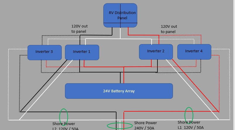
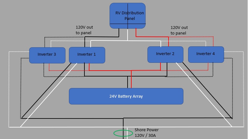
I have an RV with 50A / 240V service. Everything in the RV is 120V, the 50A service feeds each side of my panel with one leg of the shore power. In the event a 30A service is the only thing available, a 50A to 30A adapter will simply bond the two hot legs and feed them from the same 30A leg. In this case, I just need to be cautious about power consumption.

I'd like to install a couple MultiPlus 3000/24 inverters in a configuration where I have one feeding each side of my panel. I realize this isnt the best utilization of unused capacity but from what I'm able to deduct, it will yield the most flexibility with shore power configurations.

Attached are two drawings depicting a 30A and 50A situation. Both pictures also show a future 3rd and 4th inverter to increase capacity.

My questions are:

  1. If I leave inverter 1 & 2 as independent units, will they care or recognize the power coming in to each is in phase or 180* out of phase from each other? They shouldnt, right?
  2. If I add Inverter 3 & 4, would I just team then to 1 & 3 respectively?
  3. Are there any concerns with multiple inverters working independently of eachother over-charging LiFePo4 batteries?
  4. Any other considerations I may have missed?

Thanks guys!

MultiPlus Quattro Inverter Chargersplit phase
30a.jpg (56.7 KiB)
50a.jpg (64.8 KiB)
2 |3000

Up to 8 attachments (including images) can be used with a maximum of 190.8 MiB each and 286.6 MiB total.

3 Answers
Kevin Windrem avatar image
Kevin Windrem answered ·

If the L1 and L2 inverters are not configured into a system then a GX device will not control them.

As long as the total charge current configured for all inverters does not exceed you battery bank's capabilities there should not be a problem there.

A common neutral on the outputs of the L1 and L2 inverters will be a problem as the total power could exceed the ampacity of the wire when you feed the system from single phase power. But separate neutrals from each inverter (or future inverter pair) to the load distribution panel should address that.

You might also consider a 30 amp 120/240 autotransformer at the shore power inlet to make split phase power from there 120 volt 30 amp shore connection. That way everything stays the same and you can configure all the Multis into a common unit that a GX device can then control. Then too, DVCC will provide maximum charge current to your battery bank.

2 |3000

Up to 8 attachments (including images) can be used with a maximum of 190.8 MiB each and 286.6 MiB total.

ssybert avatar image
ssybert answered ·

This is helpful, thank you. The autotransformer looks interesting but with a neutral current of only 32A, I would be limiting my service capacity when connected to a 50A service wouldn't I? I have no 240V devices in my RV, everything uses a neutral.

You also bring up a good point with the GX device management. I do have a Cerbo running my current Multiplus 3000 and wondered how my BMS (which ties in to the Cerbo Gx on the CANbus) would manage DVCC on multiple inverters. The answer seems to be: they need to be grouped.


One other question... in the design proposal you suggest, with the auto transformer, are you suggesting I configure my first two inverters as a group operating in split phase? If I do this, will the 30A service present an out of phase condition for the inverters or will the autotransformer create the 180* degree 2nd leg?

1 comment
2 |3000

Up to 8 attachments (including images) can be used with a maximum of 190.8 MiB each and 286.6 MiB total.

Kevin Windrem avatar image Kevin Windrem commented ·
You would bypass the autotransformer when running off of 120/240 split-phase shore power. When you have 120 volt shore power, you'd run connect it to one hot and the neutral of the transformer and connect those to one inverter. Then connect the opposite side to the transformer and the neutral to the other inverter. The transformer creates the out of phase voltage for the "other" side. You only need a 30 amp transformer because that's all you get from a single leg 30 amp shore power receptacle.

Yes, you'd configure your inverters for split-phase operation. I'd opt for "floating phase" in case you come across 120/208 (2 legs of 3-phase) power. If you add additional inverters in the future, these would parallel the first pair.

0 Likes 0 ·
ssybert avatar image
ssybert answered ·

Ok, I think I understand now. This is an ideal configuration! I drew it up, does this look right? I think the only thing I need to do is build my own custom 30A to 50A adapter so the 30A isnt bonded to both hot legs before they come in to the RV. With this configuration, I want to be sure the 30A service only feeds the black leg in the drawing. When 50A is present, the transfer switch will lock out the autotransformer and feed the second inverter from shore L2.autotransformer.jpg


autotransformer.jpg (39.5 KiB)
4 comments
2 |3000

Up to 8 attachments (including images) can be used with a maximum of 190.8 MiB each and 286.6 MiB total.

Kevin Windrem avatar image Kevin Windrem commented ·
Yes. That seems right.

I'd use a 240 volt relay between L1 and L2 shore power as the transfer switch. That way if the voltage between the two legs is 0 it uses the auto transformer output to feed inverter 2. You wouldn't need a custom dog-bone.

0 Likes 0 ·
ssybert avatar image ssybert Kevin Windrem commented ·

Another brilliant suggestion :)


240vac-relay.jpg
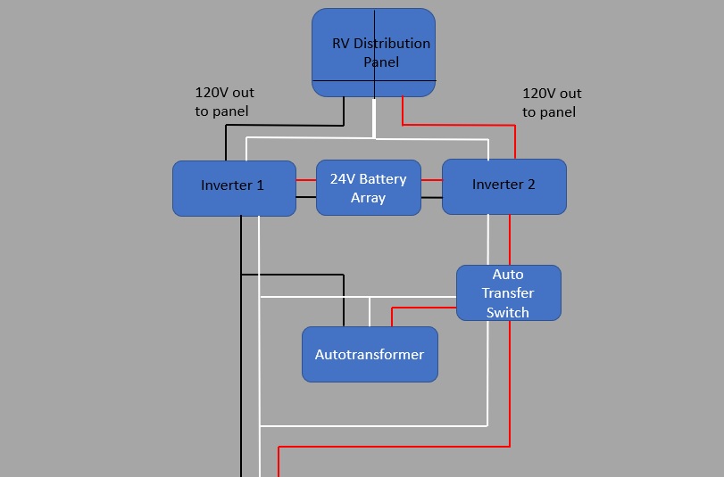
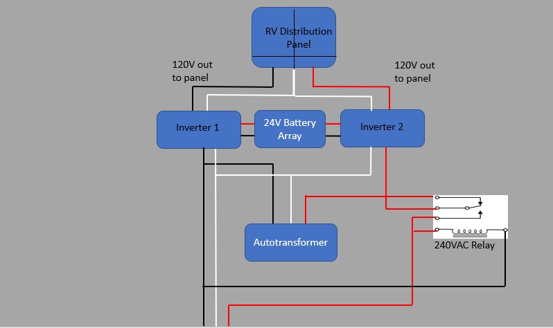
Thanks for the help Kevin. Attached is how I understand your suggestion.


0 Likes 0 ·
240vac-relay.jpg (39.0 KiB)
Kevin Windrem avatar image Kevin Windrem ssybert commented ·
That should work.
0 Likes 0 ·
ssybert avatar image ssybert Kevin Windrem commented ·

Kevin (or anyone else with knowledge in this area),


If I went with the four Multiplus 24/3000 configured for 2 per phase, and I connected to 30a shore power, what would happen without the autotransformer? Would one pair pass the 120v through and the other stay in inverter mode? This sounds like an easier solution than the autotransformer.... one pair would use whatever current was left in the 30a circuit to charge batteries while the pair on the other phase consumed it.

Is this correct? This sounds more ideal, no?


0 Likes 0 ·