question

alan-d avatar image
alan-d asked

Temperature sensors with Raspberry Pi / MCP3208

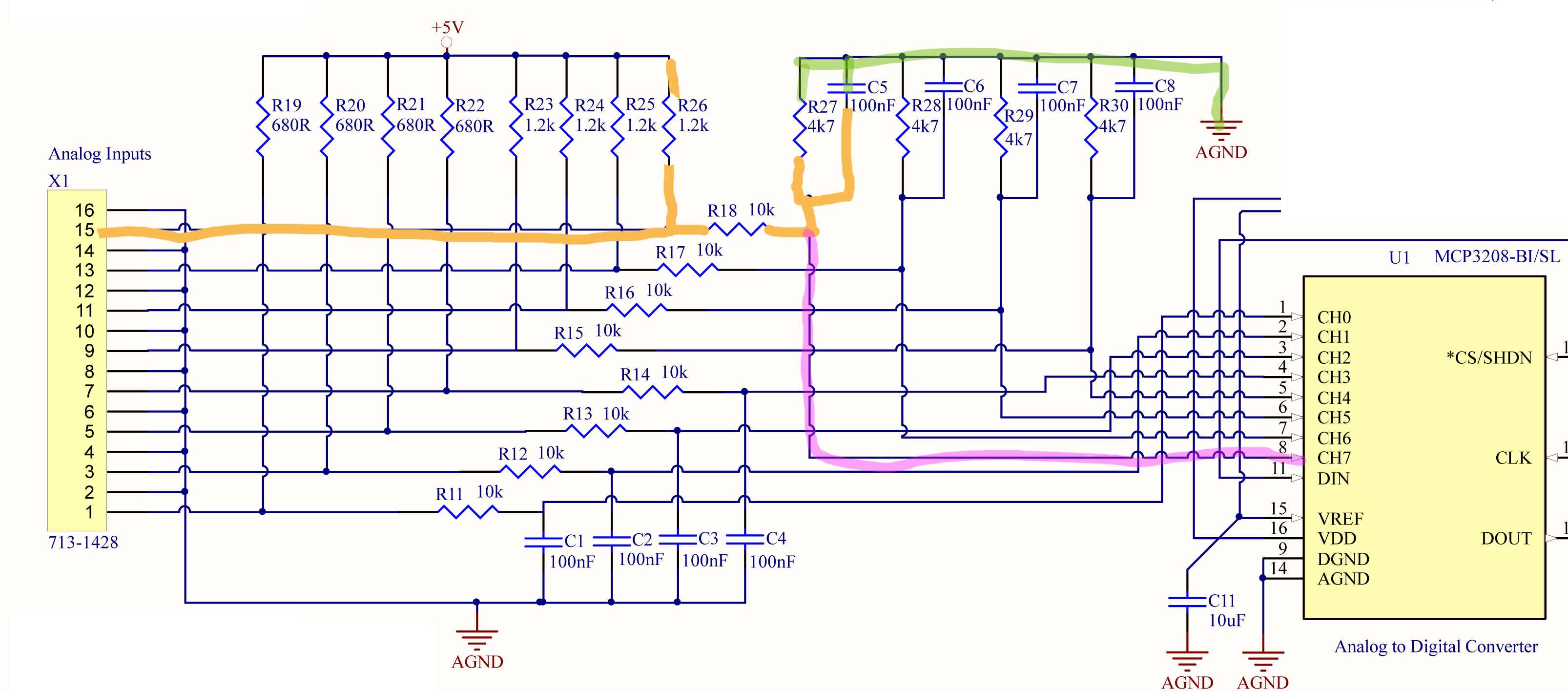
I'm trying to get a temperature sensor (TMP36) working with a Pi running VenusOS, using the MCP3208 A/D, which is recommended for this application.

I'm using a 1.8v vRef, 3.3v supply to the A/D.

Within dbus-adc.conf I have:

device iio:device0

vref 1.84

scale 4095

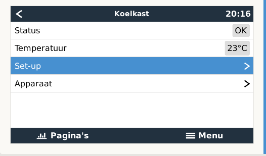
I have the A/D working, in that I can see the analogue inputs in VenusOS. Using the TMP36 sensors, I can get sensible looking temperatures with a scale of 0.3 and offset of 17 set.
HOWEVER.... if I try to use a sensor on my HW tank, after it passes around 50 degrees, Venus reports 'unknown'.

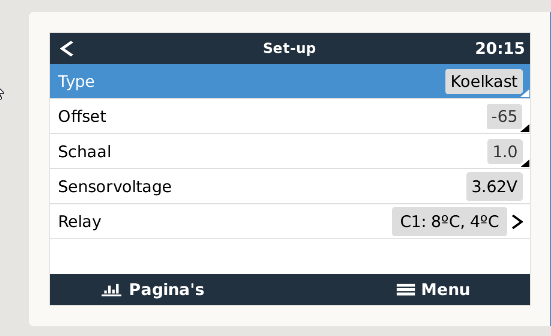
From experimentation, i've found that it's only happy with a voltage input in the range of ~0.65v to 1.05v, regardless what 'scale' and 'offset' are set to. The displayed voltage in the GUI is always higher than this however (see below).

The temp sensor outputs around 1.27 volts at 65 degrees C.

I've tried using a pot to reduce the output voltage of the sensor a bit, but it skews the voltage (and therefore temp) too much so doesn't work.

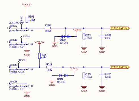
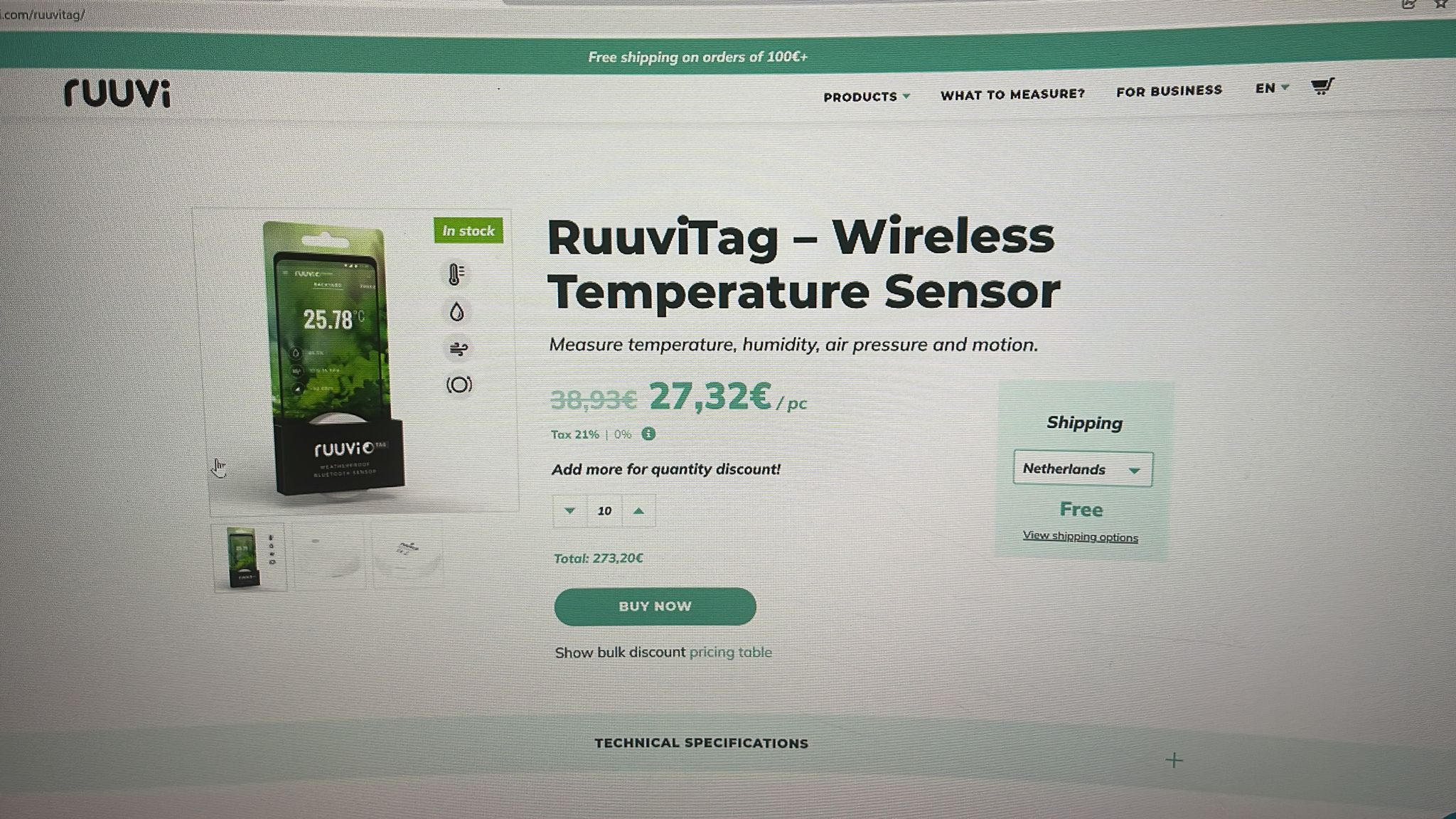
I've also tried a LM335 (which is the sensor that Victron use with the GX), but it's voltage output is even higher.

Can anyone offer any suggestions? I'm puzzled why the voltage reported in Venus is too high, and why it's only happy with such a small voltage window, which makes the offset a bit pointless.

This seems like a software config issue or bug, but I can't see what!

Here's my observed info (scale & offset set to 0)

Temperature Actual voltage Displayed voltage Displayed temperature
19.1 0.691 2.66 -7
25 0.77 2.98 23
30 0.828 3.18 44
35 0.886 3.41 66
40 0.942 3.61 88
45 0.998 3.84 108
50 1.045 4.01 127
55 1.104 4.23 ---
60 1.160 4.45 ---
65 1.27 4.86 ---


What to try next?

Venus OSRaspberry PiTemperature Sensor
1 comment
2 |3000

Up to 8 attachments (including images) can be used with a maximum of 190.8 MiB each and 286.6 MiB total.

fgs-pantera avatar image fgs-pantera commented ·

Hi @alan_d , I am experiencing the same problem you mention. Voltages displayed 4.5 times greater than actual voltages. Voltages displayed only in the range you mentioned. I guess is a software issue not hardware.

Im using MCP3208 A/D and TMP36GZ temperature sensor.

I'm using a 1.8v vRef, & 3.3v supply to the A/D.

Within dbus-adc.conf I have: vref 1.8 and scale 4095.

Have you solved the issue?

0 Likes 0 ·
5 Answers
wkirby avatar image
wkirby answered ·

What sort of front end do you have feeding the A/D converter?
VenusGX has something like this for LM335:
1628691838035.png


Circuit diagram here:
https://github.com/victronenergy/venusgx-hardware/blob/master/VE_BBB_Cape_v0.80_released.pdf


1628691838035.png (41.6 KiB)
3 comments
2 |3000

Up to 8 attachments (including images) can be used with a maximum of 190.8 MiB each and 286.6 MiB total.

alan-d avatar image alan-d commented ·
I have a 10k resistor and a 220pf capacitor to ground (with the TMP36).

When I tried the LM335 I added a 2k pull-up resistor.
I can try their circuit, if you think that may help here?

0 Likes 0 ·
jeroend avatar image jeroend alan-d commented ·
It would help ;-) I have it like that too and temp readings are accurate
0 Likes 0 ·
alan-d avatar image alan-d jeroend commented ·

I've built the Vicrton circuit above, but it's still not working. With the sensor around 22°C I see around 0.92v on the A/D input, yet the software reports ~0.78v and shows a temperature of '--'. Scale is 1.0 and Offset 0.

vRef is 1.82 volts

dbus-adc.conf:

device iio:device0
vref 1.82
scale 4095
tank 1
tank 2
temp 3
temp 4
temp 5
temp 6
temp 7

A/D currently has a 5v supply, didn't seem to help changing from 3.3v.

Any suggestions?

0 Likes 0 ·
Marcel avatar image
Marcel answered ·

Hi @alan_d ,


I'm thinking about building the same circuit for temp reading. Have you got it working with LM335 ?

If so, can you provide me with a simple schematic?


thanks for your help.

regards,

Marcel

2 |3000

Up to 8 attachments (including images) can be used with a maximum of 190.8 MiB each and 286.6 MiB total.

alan-d avatar image
alan-d answered ·

Apologies, I forgot to reply the other day.
I didn't get this to work. Don't know if my LM335's aren't giving the expected output (but I can see the voltage change with temp when measured) or if the circuit diagram above is wrong. I've given up with it for now, will re-visit sometime in future.

1 comment
2 |3000

Up to 8 attachments (including images) can be used with a maximum of 190.8 MiB each and 286.6 MiB total.

Marcel avatar image Marcel commented ·

Hi @alan_d,


Thank you for your reply. Can you tell me what voltage readout you have?

My setup is a RaspberryPi with the ExpanderPi hat. I have them activated in the Venus software. (current software is 2.80_17_large22) I even have the data available on a second Pi with Grafana.

Now for me it's time to get the correct readouts for the analog inputs.


I build my circuit following the schematics of @Rob Duthie but I don't seem to get the correct readout.

As I'm not an electrical engineer. I've build the ciruit on some testing board following the exact layout of the schematics.

Input voltage for the circuit is the same as the Pi 5V. The sensorvoltage is 1,15V according to the dashboard.

When I measure the circuit with a multimeter it has a readout of about 0,84V

I think I made a mistake with my soldering, but don't know where to start.

When I looked at the specifications of the LM335 it should be connected to the middel and right leg when facing the flatside of the sensor.

img-1623-custom.jpg

I've attached a part of the schematic by @Rob Duthie and simlified it by drawing with colors the path.

circuit.jpg

Thank you for your help.


regards,

Marcel

0 Likes 0 ·
img-1623-custom.jpg (125.1 KiB)
circuit.jpg (1.2 MiB)
Paul B avatar image
Paul B answered ·

I dont know if this will help but have you looked at these temp sender ??? as they now connect to the victron cerbo

1639801760542.png


1639801760542.png (4.4 MiB)
1 comment
2 |3000

Up to 8 attachments (including images) can be used with a maximum of 190.8 MiB each and 286.6 MiB total.

Marcel avatar image Marcel commented ·
Hi @Paul B,


Thank you for your reply. There indeed are some alternatives when it comes to the sensors.

As I allready started with the Analog board, I have my hopes up for getting them to work.

regards,

Marcel


0 Likes 0 ·
vitor avatar image
vitor answered ·

Hi.

The feed voltage for the ExpanderPi must be very stable.

I change the dbus-adc.conf vref to be equal to the feed voltage, in my case, equal to 5 volts (with a 7805 voltage regulator). If the volts fall above 5 volts, the temperature change.

That way the temperature works fine.

1 comment
2 |3000

Up to 8 attachments (including images) can be used with a maximum of 190.8 MiB each and 286.6 MiB total.

Marcel avatar image Marcel commented ·

Hi Vitor,


I just red your post and it got me thinking: I use a 12V powersupply with a DC/DC converter to 5V It powers the Pi and ExpanderPi; It can also handle a touch display via USB from the Pi.


Finally after your post I now got it working! I needed to adjust mt VREF value in dbus-adc.conf.

It now has a reading, but it is a bit of scale. remote-console-on-lan.png

remote-console-on-lan1.png


regards

Marcel

0 Likes 0 ·