question

raymiller avatar image
raymiller asked

SmartShunt 500A base very fragile

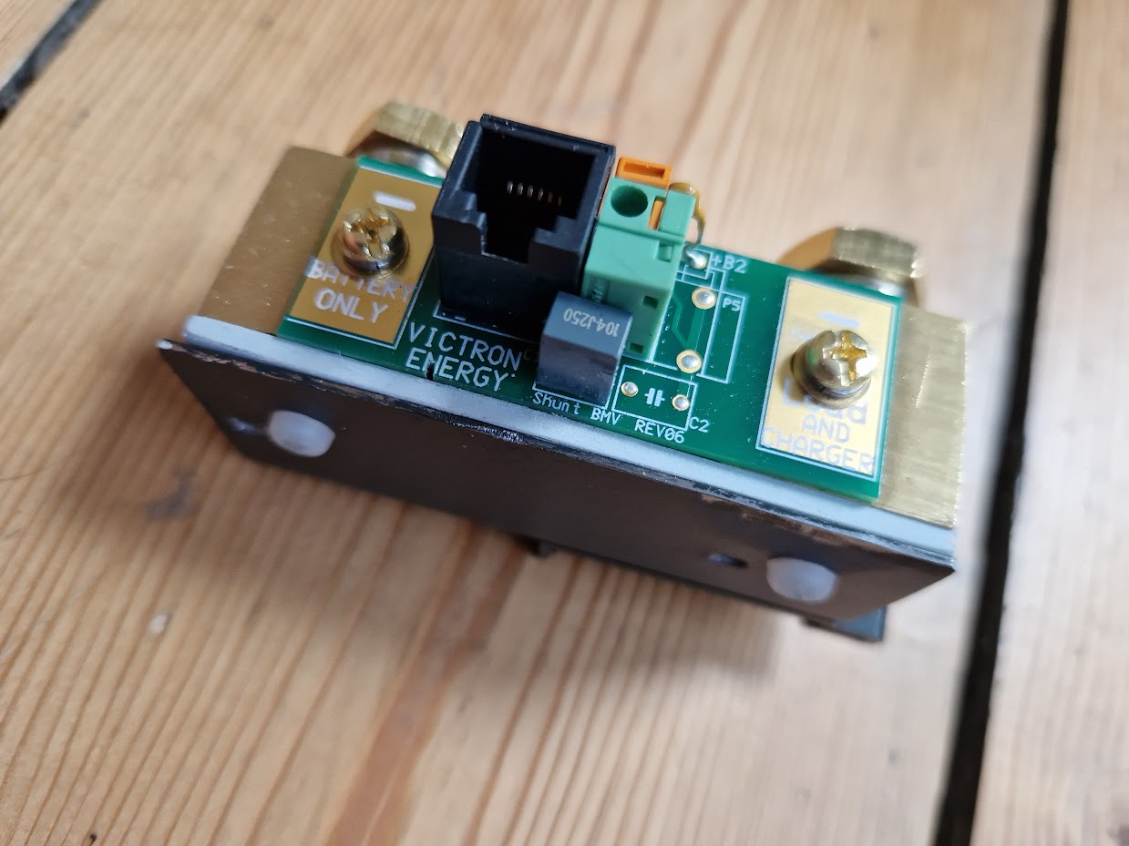
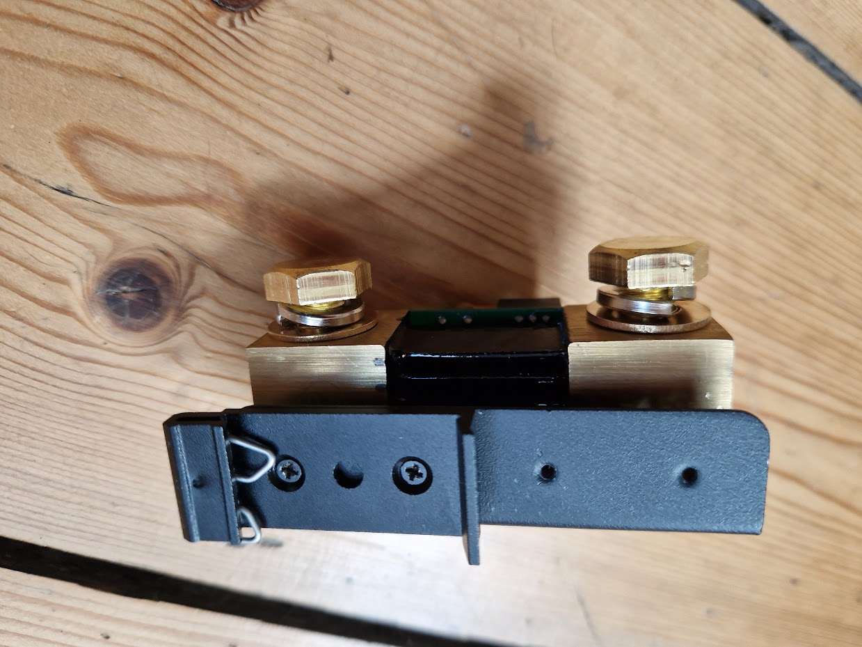
I have purchase two Victron Products with the 500A shunt which has a black insulating mount, in both cases I've found that the mounting base is very fragile and brittle. The 500A shunt being a two 25mm brass blocks joined has significant mass, my latest unit had the mount cracked on delivery, while my first unit (BMV712) I managed to crack on installation when mounting.

The construction of the black base moulding has significantly hollowed out sections to reduce the amount of material but due to the brittle nature has no flexibility so cracks under any mechanical stress. As any cables or components which will be connected to the 500A shunt are also likely to be sizeable and heavy and the consequences of mechanical failure may be great, improving the mechanical strength and robustness of the base commiserate with the expected forces is highly desirable.

My repair consisted of filling the voids in the mounting with two-pack epoxy. This seems to add the required durability to the black base.

I'm sure I'm not the only customer which has experienced cracking issues with 500A shunt base. Please Victron could look into changing the design of the base to be substantially more robust than the current design and remove a point of failure would improve on an excellent product.

BMV Battery MonitorSmartShunt
8 comments
2 |3000

Up to 8 attachments (including images) can be used with a maximum of 190.8 MiB each and 286.6 MiB total.

chuckvb avatar image chuckvb commented ·

Same thing happen to me. I'm going to try you epoxy idea. Also, I'm going to see if the base is removable. I've got a great ptfe material that tough. I don't get the weak base and heavy cable design. It's a flaw.

0 Likes 0 ·
Alexandra avatar image Alexandra ♦ chuckvb commented ·

@ChuckvB

There should not be unsupported weight on lugs or unsupported and un fixed cabling in any installation.

That is poor installation and not likely to regulation either.

1 Like 1 ·
chuckvb avatar image chuckvb Alexandra ♦ commented ·
It had to do with cracking during install. The base cracked when the screws with washer were tightened. Now for you "unsupported weight" comment. In an rv with 0000 wires connected to the 3/8 lugs you will get stress just from the wires as 0000 will tension the part and vibrations going down the road. They build a part with 3/8 lug mounting for the big wires and then add a flimisy base which also is leveraged. Bad mechanical design and that's coming from a Aerospace Mechanical Engineer with Stress analysis experience.
2 Likes 2 ·
Alexandra avatar image Alexandra ♦ chuckvb commented ·

I guess my qualification in the comment then is experience. I have installed quite a few on installs and not broken even one. And I know plenty out in the field both professional and (some fairly ham fisted) diyers who haven't broken theirs.

There shouldn't be anything 'leveraging' on it, it is an instrument.

0 Likes 0 ·
chuckvb avatar image chuckvb Alexandra ♦ commented ·

Yes, it's an instrument but not one passively monitoring the system from aside, it's got the main returns connected to it. It needs to be as robust as the rest of the equipment that handles those cables. No good if you install and it break after a few months on the road. Your experience gets you out the door...

1 Like 1 ·
nesswill avatar image nesswill chuckvb commented ·

Good idea and worth a try.

Everybody's experiences can be different, i have fitted x3 with no problems but this could be because mine are on busbar.


Did you tighten the bolts/screws to the recommended torque? (even if not stated you can work it out by the size, material of the bolt and supported weight to what you are tighten to)

But i also might be down to the orientation vertical horizontal. AV Mounts might help in some installations.

But as with everything maybe it can be made with a more durable base but would you pay the extra $50 each?, some might some might not.

0 Likes 0 ·
klim8skeptic avatar image klim8skeptic ♦ nesswill commented ·
Maybe there is a market for someone smart with a 3D printer.

Super rugged, stylish and practicle replacement shunt bases?


1 Like 1 ·
nesswill avatar image nesswill klim8skeptic ♦ commented ·

Great minds think alike klim8skeptic.

0 Likes 0 ·
2 Answers
chrispi avatar image
chrispi answered ·

I installed countless also non Victron shunts till 1500A and can state that the Victron are one of the best qualities out there but yes rideon for example provide larger surface bases. But if they crack during installation then you are using the wrong screws or bolts maybe even with a cone.

To install them correctly:

1)use the big head flat screws with the correct max size the mounting holes allows and I use max sized washer additionally and then screw down with right toque spec on your powerdrill. That is sufficient for max cable size with lug, eg a 500A shunt has cont 320A which is a 150sqmm cable under all conditions..I install now in bluewater cruising boats=worst environment you can have as constant vibrations and forces plus salty air.

2) never lug stack on a shunt, yes if space constraints forces to stack then max 2 with special stacking lugs! In a 90 or more degrees angle. Correct way to do add a small busbar that has a support at the other end too to the shunt and connect the multiple cables to the busbar.

3) use a pp board as mounting base for electric install and screw or/and glue it with sikaflex to the chassis, hull…that cannot catch fire even in a massive short, isolates all components and give an even surface for mounting.

4) a tip and trick I use: the 500A Victron and rideon shunt (as well as the 700A rideon one) have the exact same height as NH 2 and NH3 fuses. NH fuses have a massive ceramic base with m8 holes, that screwed down is solid like a rock. You need a main battery and cable fuse anyhow as well as a disconnection switch, the NH is both with 100kA short circuit that’s enough for biggest lithium battery.

So if you install in extreme conditions like boats or off-road RVs you use on input side a NH fuse holder with a disconnection knife and on the other side the NH main battery fuse and inbetween the shunt. The connections in and ouput are now on super solid bases AND this combo has the self cooling capacity to run at 500A continuous with a 500A shunt and not introducing any of the heat in the installation. I connect then right away the main busbar to the NH fuse…cannot be more sturdy.

What I see when support lithium install on boats are the following:

spax screws in 3,5mm with cone when hole allowed 6mm drilled down with max torque spec your powerdrill has, sure it cracks.

5 normal lugs stacked on top of the shunt with cables all going to one side, first connection is bad and that heats up like an induction stove and 2nd the lever forces the plastic base cannot deal with and sure base cracks

Shunt is screwed down on an uneven surface introducing twisting forces into base…sure it cracks and sometimes even the resistance blades partly disconnect means from heating up till unprecise data.


2 |3000

Up to 8 attachments (including images) can be used with a maximum of 190.8 MiB each and 286.6 MiB total.

ben-barker avatar image
ben-barker answered ·

I realise this is an old post, but it seemed relevant:


I had a need to install a shunt in a relatively tight space, ideally to existing DIN rail. The length of the standard base (120mm) and the need to bolt it to a surface both didn't really work for my needs.

I removed the factory installed plastic base (held on by two small brass screws), then secured the shunt to a 90 degree DIN rail adapter, insulating the shunt from the metalwork using nylon screws and a plastic spacer plate


I will need to make sure the cables are run such that they can't force the unit off the DIN, but that would be normal good cable routing practice anyway


1711201617697.png

1711201628957.png


1711201617697.png (1.4 MiB)
1711201628957.png (1.4 MiB)
2 |3000

Up to 8 attachments (including images) can be used with a maximum of 190.8 MiB each and 286.6 MiB total.