question

bjorn-n avatar image
bjorn-n asked

Solar inverter does not like MultiPlus-II impedance

I have two solar inverters connect to the "critical loads" output (AC-OUT1) of the MultiPlus-II in an off grid situation. This means the MultiPlus-II is disconnected from the grid, i.e. nothing connected on AC-IN1.

The inverter of the MultiPlus-II is providing a stable 50 Hz 230V grid on AC-OUT1 so the solar inverters are seeing a grid (provided by the MultiPlus-II) and are powering on. They "monitor" the grid for about 30 seconds like usual and then they should switch to producing energy and feeding it back into the grid. At this point however, both the solar inverters display a similar error message.

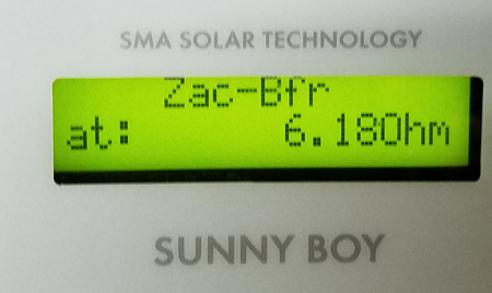
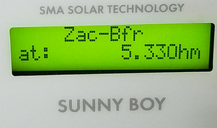
Zac-Bfr at <some value> Ohm

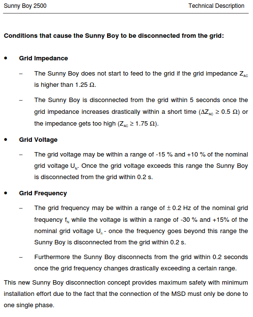
According to https://my.sma-service.com/s/article/Blink-code-3-dZac-Bfr-dZac-Srr-Zac-Bfr-Zac-Srr?language=en_US, this indicates that the impedance of the grid (provided by the MultiPlus-II) is too high.

The solar inverters then shut down (or re-initiate), monitor the grid for some time and end up display the same Zac-Bfr message with a slightly different impedance value in Ohm.

I have tried connecting only solar inverter 1 or only solar inverter 2 to the MultiPlus-II but the result remains the same Zac-Bfr message.

Why don't my solar inverters "like" (the impedance of) the MultiPlus-II grid and what can I possibly do about it?

screenshot-at-2021-05-29-08-19-24.pngscreenshot-at-2021-05-29-08-19-31.png

Multiplus-IIoffgrid
2 |3000

Up to 8 attachments (including images) can be used with a maximum of 190.8 MiB each and 286.6 MiB total.

2 Answers
Matthias Lange - DE avatar image
Matthias Lange - DE answered ·

This is not a Victron problem.
The Sunny Boy is doing what he should in default configuration.

If I remember correctly the Sunny Boy can't be used off-grid with the default settings.
You need to adjust the grid settings of the Sunny Boy using the Grid Guard-Code.
Contact your installer or SMA to get that code and the correct settings.

BTW What Multi and Sunny Boy do you have? Pay attention to the factor 1.0 rule:
https://www.victronenergy.com/live/ac_coupling:start

3 comments
2 |3000

Up to 8 attachments (including images) can be used with a maximum of 190.8 MiB each and 286.6 MiB total.

bjorn-n avatar image bjorn-n commented ·

Victron MultiPlus-II 3000 and 2x SMA Sunny Boy 2500. I was hoping the MultiPlus-II would be able to create a stand-alone grid that does not trip the solar inverters anti-islanding protection. For clarities sake: when I'm doing this standalone grid / off-grid grid, I'm totally disconnect from the elektricity grid.

In accordance to DIN VDE 0126-1-1, there are three accepted methods of achieving this, as follows :
1.  Grid impedance measurement
2.  3-phase grid voltage monitoring or
3.  the oscillating circuit test

Until the end of 2007, we used grid impedance measurement at SMA, since this is a very reliable method of detecting stand-alone grids.

If I can somehow switch to the oscillating circuit test, would this make a difference?

Guess I will have to pick up that RS485 interface project again to change settings on those 10+ year old solar inverters.


I am aware of the factor 1.0 rule. When testing, I only connect both SMA inverters before 9 o'clock or after 15h00. Or If I'm doing tests between 09:00 and 15:00 I only connect one of the SMA solar inverters to stay below 3000 VA of the MultiPlus-II 3000


0 Likes 0 ·
Matthias Lange - DE avatar image Matthias Lange - DE ♦ bjorn-n commented ·

The high impedance is coming from the toroidal transformer inside the Multi, there is no way you can change this.

0 Likes 0 ·
bjorn-n avatar image bjorn-n Matthias Lange - DE ♦ commented ·

Wouldn't, at least in theory, a suitably sized capacitor (in series) be able to counter the effect of the toroidal transformer (inductor)?

inductive reactance Zl = 2*pi*frequency*inductance

capacitive reactance Zc = 1 / (2*pi*frequency*capacitance)

inductance Z = sqrt(R^2 + (Zl-Zc)^2) = 6 Ohm

Let's suppose R is zero. It should be very low anyway. Then Zl-Zc = 6 Ohm, so I would need Zc to be 5 Ohm more than it is now. So Zc = 5 Ohm = 1 / (2*pi*frequency*capacitance)

so C = 5 Ohm * 2 * pi * 50Hz = 1570 Farad. Which would be a capacitor the size of a car? :-)
Not sure about the calculations here, this value seems like an extremely big value...

Even if this could work, this huge capacitor would probably have an adverse effect on the power factor... Reminds me to learn more about RLC circuits in AC circuits.

0 Likes 0 ·
Paul B avatar image
Paul B answered ·

No firm answer here as you would need to contact the SMA supplier.


but try some different country codes in the sunny boy


when they turn off whats the Hz figure

have you set the Victron ESS up correctly or what assistant setting's have you done.

please advise all your settings and some sample outputs on AC1 out when shut downs occur

like are the batteries full and thus the multiplus hz is increasing then telling the SMA units to turn off

if this is all staying at 50hz then contact you SMA dealer for setup advise


1 comment
2 |3000

Up to 8 attachments (including images) can be used with a maximum of 190.8 MiB each and 286.6 MiB total.

bjorn-n avatar image bjorn-n commented ·

The solar inverters do not complain about frequency or voltage. On the contrary, when the solar inverters are in "monitoring mode" for about one minute, they show a frequency of 50Hz and voltage of 230V provided by the MultiPlus-II.

So, at that point in time, everything is fine and they connect to the MultiPlus-II grid. Apparently the first thing the solar inverters do is a grid impedance check. Which fails so they immediately disconnect again.

So the issue is that the SMA inverters see the difference between the "real" grid and the standalone grid provided by the MultiPlus-II. If the MultiPlus-II would provide a (standalone) grid with an impedance of less than 1.25 Ohm, this wouldn't be an issue.

I have tested this at different state of charge of the batteries (approx. 40% and 80%). State of Charge does not make a difference. The resulting behaviour of the SMA solar inverters is the same.

screenshot-at-2021-05-30-12-52-55.png

As far as ESS goes, I believe I have it setup correctly. It works fine when I connect the whole system to the grid. I can charge/discharge the batteries at will.

0 Likes 0 ·