Hi everyone, We have experienced issues with Victron inverters. Since the marina installed ground-fault relays (breakers) on the docks I have 4 customers that are tripping the GFI breakers on the dock and the marina office is requiring them to get it fixed. The Problem with all of them is the Victron inverter. I just installed a new one but as soon as I ground the chassi and inverter turns on it trips the dock GFI. Same problem on other boats. If the Grounds are removed from the inverter problem is solved and GFI does not trip. Just For reference The marina just got the GFI system installed and it is set to 0.2 Amps. Is there a way to fix that problem and what should I tell the owner who just paid for the new Victron inverter that got installed but it can`t be grounded. The only way to work is if there is no ground to the inverter neither for input or output or chassis.
asked
Ground Issues with Victron MultiPlus 24V DC - 3000W
You don't say whether the GFI trip occurs when the inverter is using the AC input and passing through power to the loads, or if it is when the inverter switches away from AC input and is inverting.
GFIs measure the differential current between hot and neutral. This can be caused by:
- leakage in some faulty device or wiring.
- filter capacitors at the AC input to safety ground
- a neutral to safety ground short which causes some load current to flow through the safety ground connection
I would investigate #3.
There should be EXACTLY one neutral/safety connection and that's at the source of the power. In the case of shore power, this happens at the service entrance. In the case of the inverter running without AC input, that "bond" occurs inside the inverter by closing the ground relay.
In a system with split-phase shore power and a single inverter, one leg is fed from the output of the inverter and the other is fed directly from shore power. The shore power neutral ends up connected to the inverter's AC output neutral in the power distribution panel.
When the inverter is passing AC input to it's output, it ties the input neutral to the output neutral through the AC input relay. The ground relay will be open in this case. So from a ground fault standpoint, all should be well. However, some neutral current will flow around the inverter via the shore power neutral. This could cause unwanted current flow inside the inverter.
When the inverter goes to invert mode, the AC input relay opens and the ground relay closes, but remember the shore neutral is tied to the load neutral in the power distribution panel. With the ground relay closed, there is now a connection between neutral and safety ground down stream of the GFI and the GFI will trip.
Disabling the ground relay will remove the neutral/safety ground connection, but there is a problem when shore power is not connected. With shore power disconnected, there is no neutral/safety ground connection for the inverter's output. This probably won't hurt loads but is against most electrical codes since voltage can appear on an unfused conductor.
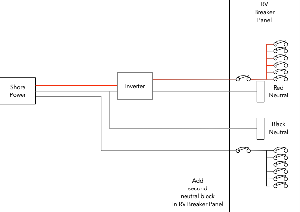
The correct solution to this problem is to keep neutrals separate for each leg. It should be fairly easy to add a second neutral busbar inside the power distribution panel as I've shown below
Disable "Ground relay" from inverter settings (if it is enabled) and see if it solves this issue.
seb71 - do you know of a way to disable the ground relay without using a laptop? I am trying to figure out how to move between gfi and non gfi supplied locations and not have to use a laptop each time I need to disable the ground. Can a cerbo gx do this or are there other ways to accomplish this?