I have a Cerbo GX and Color GX screen. I want to add temperature sensors for my two batteries. 1. Does the sensor go on + or - terminal of battery? 2. Appears only one input on Cerbo and there are two wires from sensor? How do I connect wires to Cerbo unit. Thanks!
asked
Simple wiring diagram for temp sensor inputs Victron ASS000001000 to Cerbo GX
There are four temperature inputs on the Cerbo.
Here you can see I have connected just two temperature sensors to it on inputs 1 and 2:
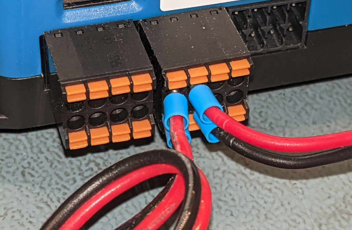
On the other end, connect the sensor its self to the negative battery terminal.
This sensor lug does not need to be connected to anything of you are not measuring battery temperature. Leave it floating in mid air if you want to measure air temperature.
Thank you! This is exactly what I was looking for. Much appreciated.
Very helpful. How do I activate sensors. they are not showing up on color 50
Hi!
See the Settings -> I/O -> Analog inputs menu.
Have we not explained that in the manual?
Hello @cwvandy,
1. That temperature sensor is electrically isolated, so you can put it wherever you like, it doesn't even need to be on the terminal of the battery at all to function.
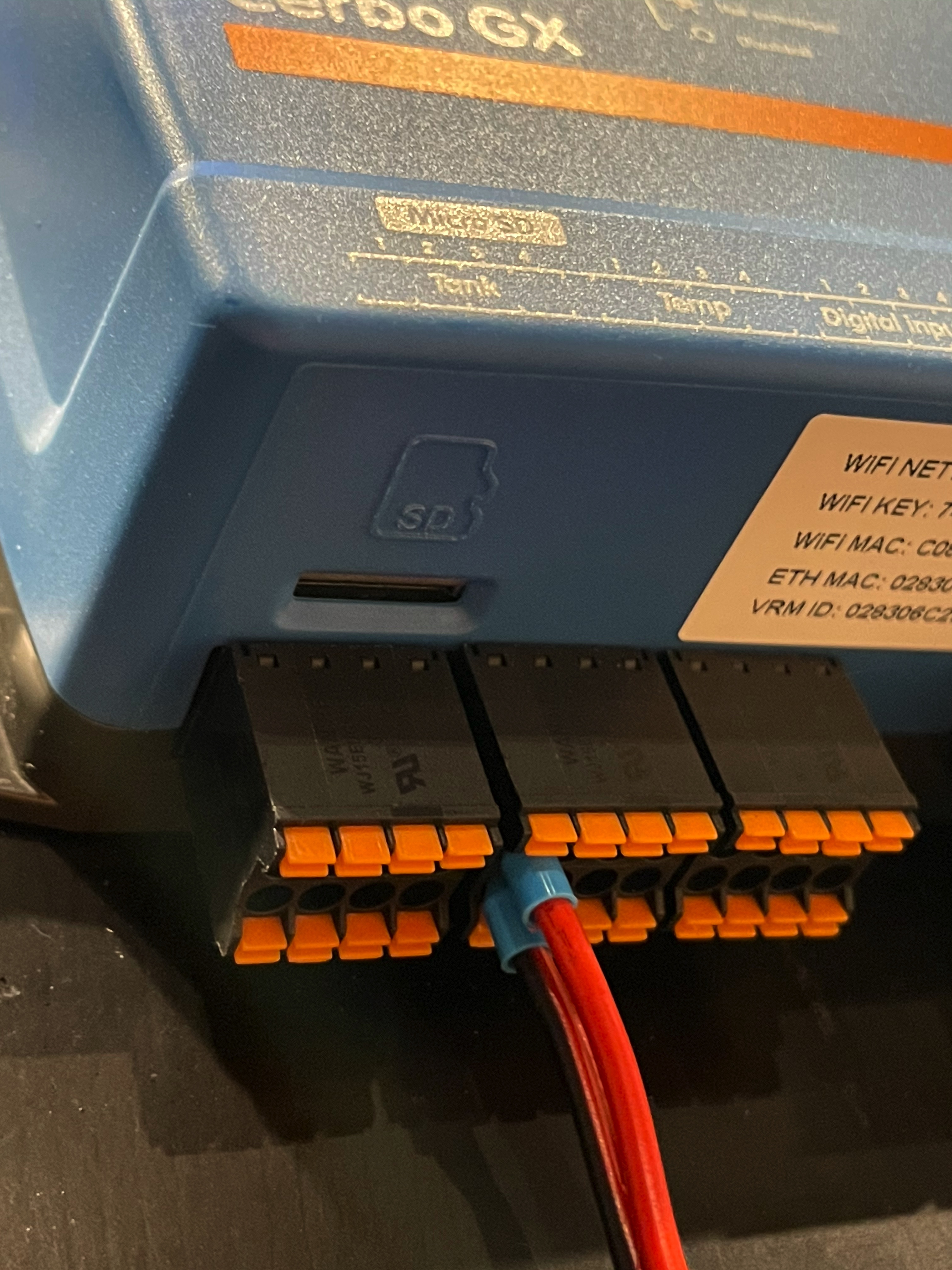
2. When making the connection you need to have the included terminal block of the Cerbo GX, then make the connection like this; with the red wire on the top and the black on the bottom.
@Guy Stewart (Victron Community Manager)
make the connection like this; with the red wire on the top and the black on the bottom
This should be added in Cerbo GX manual (chapter 2.9).
@Seb71, I'll note that the "red on top, black on bottom" is alluded to on the top of the Cerbo itself, where it notes that "Data" is the top row and "Ground" is the bottom row... but I'll definitely +1 the suggestion to add that information into the actual manual, particularly given how small the print is on top of the Cerbo!
@Justin Cook - Bay Marine Supply USA
Ha ha. I had to take a closer look. I haven't noticed those Data/Ground markings on the Cerbo GX case until now.
@Seb71 LOL, honestly I was right there with you... I only noticed them after I'd already taken a multimeter to the pins to verify the polarity... pulled out the test unit, powered it up, tested polarity at the pins, and was putting the test unit back in its box when I noticed the print and facepalmed :-P
Yes, this image it must be added to the manual. Someone really lost concentration when they wrote this section of the manual.
Is it possible to have the Temperature Readings (for the 4 Analog Inputs) to show on the Nema 2k network?
Hi, no its not, sorry.
In the Cerbo manual there is a list of supported data. Tank levels are included. Temperatures are not.
@Guy Stewart (Victron Community Manager)
And from the same Cerbo GX manual:
It is possible to adjust the temperature offset and scale.

These two settings are missing from my Cerbo GX (in FW 2.60 and also in FW 2.63).
My temperature sensor is measuring high, so I would need to use the offset to correct the displayed temperature value.
Edit
I found the answer to this: those two settings are only available if you have superuser permissions. Strange decision, but after enabling root access I could correct/offset the temperature value.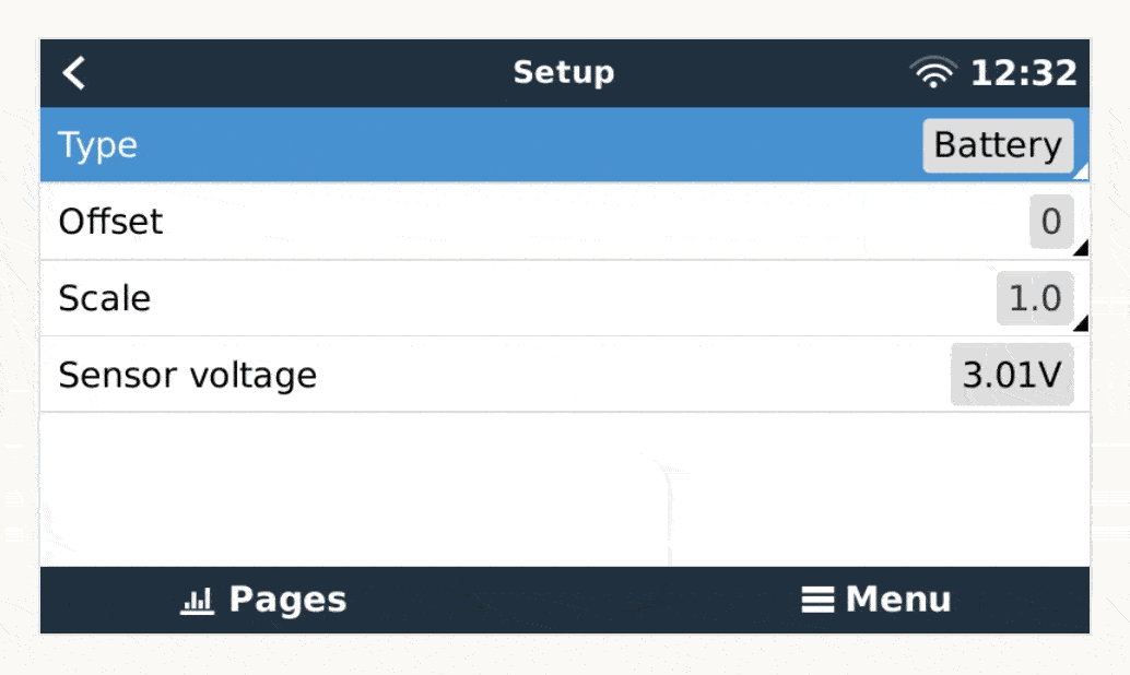
Hi, they’ll be more generally accessible in one of the future firmware updates.
Thanks much. Any advice on how to active sensor. Plugged into cerbo properly but does not show up on settings in color gx 50.