I'm unable to find any detailed information on the output power of the MultiPlus with regards to its cleanliness and sine wave stability. What kind of sine wave does it output, and is this unit suitable for electrical equipment such as speakers for instance. Any info would be appreciated.
asked
MultiPlus 48/3000/35 output current cleanliness?
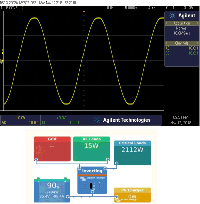
It is s true sine wave inverter, tried it on an oscilloscope at work. Even under load it is stable.
My husband is a bit of a sound enthusiast, has built his own amplifiers with studio monitors from a recording studio. Best sound from he amps built is when we disconnect from grid power and let the Victron determine the power quality.
There is no hum or other whining sound heard (if there are no issues with the amps or cables themselves).
Thanks Alexandra, this is good info to hear. I had one of these units installed in my studio, and tech here at Victron also confirmed a <2% THD value for the output. I'd love to know more about how this sine wave is formed. Is it stepped, and then smoothed? Not a lot of info on the website though.
Sadly, I was under the impression that the current always passes through the inverter, however have now discovered it passes grid power through the inverter untouched between + & - limits, so I'll need to review the situation and install additional power conditioners.
It uses the PWM sinewave technique.
Johannes explains how it works in this video:
https://www.youtube.com/watch?v=UPfUn5ki7OM
That's not how it works at all.
There are no output capacitors - the output is AC.
The capacitors inside the MultiPlus are at the DC input.
There are no steps, the MOSFETs are either fully on or fully off. Operating the MOSFETs in the linear region (betwween on and off) would be very inefficient.
Like I said earlier, it's PWM sinewave. It is a common technique for creating a pure sinewave. The large iron core step-up transformer at the output also filters out any high frequency harmonics.
Yes I understand how it works, stepped isn’t the best term to use as it can be easily misunderstood/misinterpreted.
The fets are switched in varying lengths of increasing then decreased ON time via PWM, this creates a stepped voltage increase and decrease over time i.e AC sinewave.
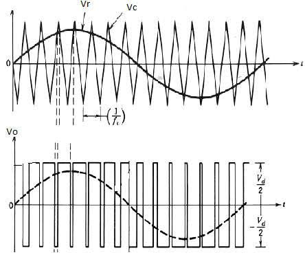 By the video it looks like they use a 20Khz resolution. This would work out to 200 pwm pulses (voltage resolution at output) per half wave. There will be a dead time between the fet switch, the output is more likely rough, so there will almost definitely be a LC filter in there for smoothing and harmonic rejection, I haven’t opened up a unit and looked.
I wonder if the victron designers are looking at replacing the Mosfets with GaN HEMT’s for a increase in efficiency.
Thanks so much for these detailed answers. This inverter is fascinating, especially the idea of sync up FET's cycling so quickly. I'm very interested in the post FET stage as well now. What does the coil look like, how is it wound etc. Clearly these FETs generate some heat, thus requiring quite a lot of cooling for these inverters.
There are a few pics here and in the video from johannnes
https://community.victronenergy.com/questions/12532/quattro-and-lightning.html
There's some info on THD in the certificate.
https://www.victronenergy.com.au/upload/documents/Certificate-G59-3-1-MultiPlus-and-Quattro-3kVA,-5kVA,-8kVA,-10kVA-and-15kVA.pdf