question

raffadee avatar image
raffadee asked

220a battery protect

Hi,


I’m fairly new to this so please forgive me if I sound stupid lol

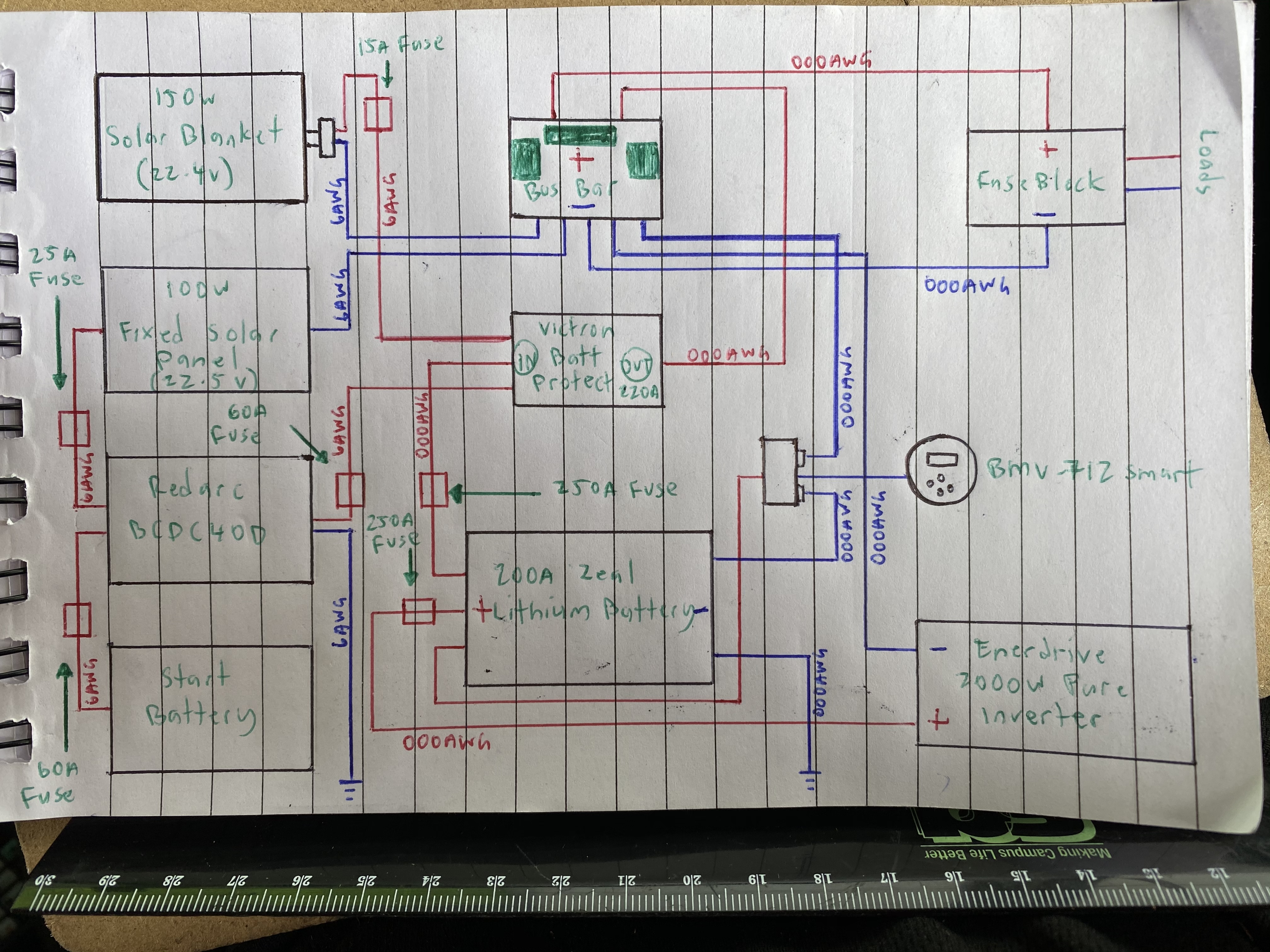
I just wanted advise on my wiring and if everything is correct, especially the wiring to and out of the 220a battery protect. I’ve attached a picture of what I plan to do


I want to integrate the bp in my 12v setup. I read that I couldn’t connect the bp inline with an inverter so I figured i would be ok to connect it directly onto the aux battery?


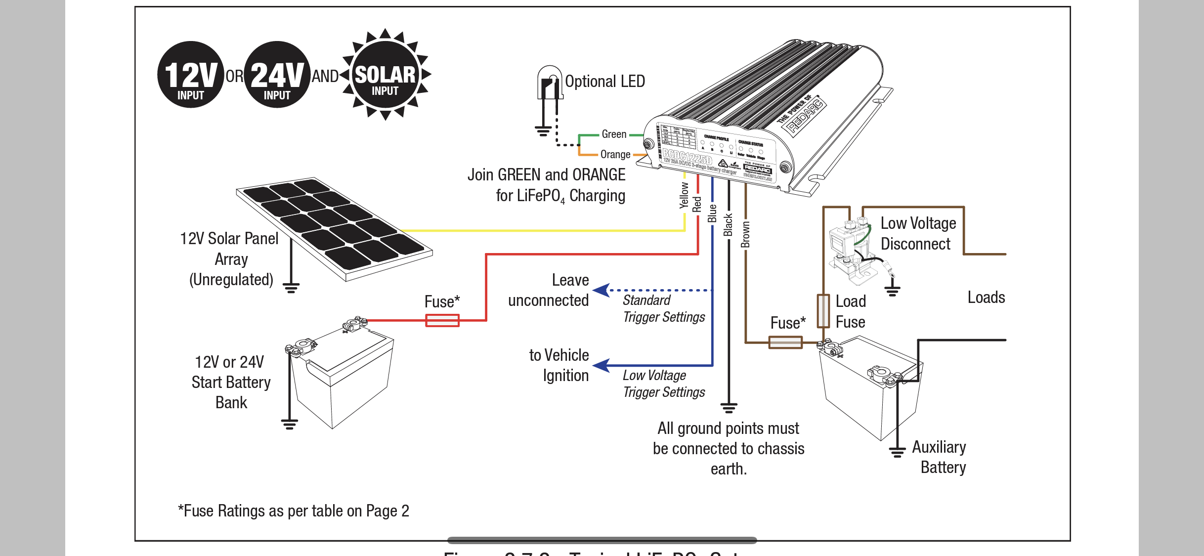
With my battery charger (redarc bcdc40d - wiring diagram included in picture below) it states that the low voltage disconnect (which in this case is the victron 220a batt protect) should be AFTER the battery and then to loads

Example: batt charger/solar regulator - aux batt - bp - loads


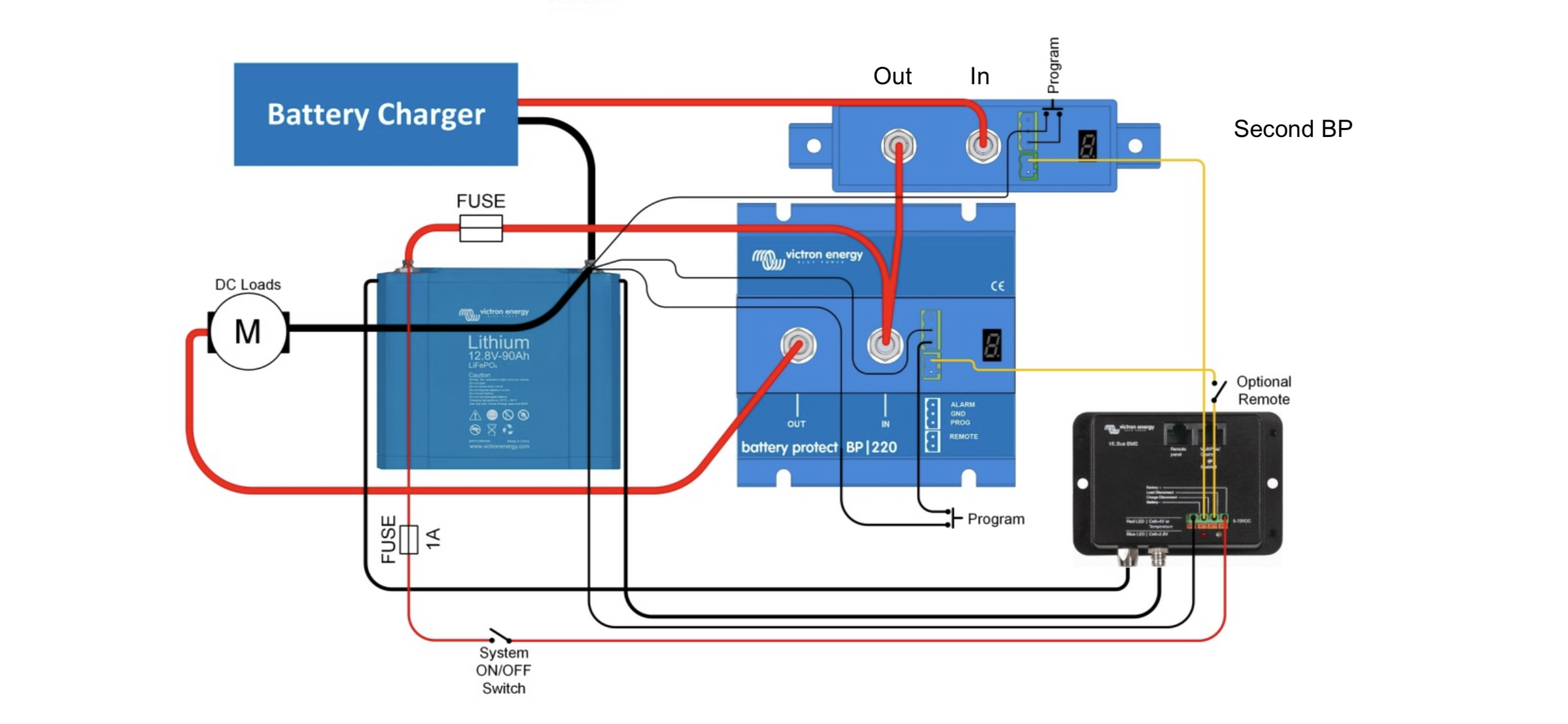
Victrons wiring diagram states that bp should be BEFORE the aux battery then to aux battery and then to loads.

Example: batt charger/solar regulator - bp - aux batt - loads


Also my bcdc charger has an inbuilt solar regulator in it so I’ll be connecting a fixed solar panel directly to that, but if I wanted to connect an extra solar blanket with its own regulator, would I connect that directly to the bp or directly to the battery.


I’ve heard that solar panels and maybe even battery chargers can make current go back through in the opposite direction so I’m basically trying to figure out in which order the bp goes and what I connect before/after as I want everything to flow in one direction through the bp (in to out) like the instructions say.


I’m also thinking of scrapping the bp altogether and connecting a relay to the bmv-712 smart to trigger a low/high voltage cut off but I can’t seem to find a simple diagram on how I would wire that up. If anyone has one, I would be extremely grateful if you could share that with me.


Regards,

Rafael


0631c4fb-a3f2-4c00-8492-2b471e0c651f.jpeg6fe5d468-3578-473f-83e8-06897a4384f0.png4a621470-0b90-4951-9564-128cdd7b725e.png

Battery Protect
2 |3000

Up to 8 attachments (including images) can be used with a maximum of 190.8 MiB each and 286.6 MiB total.

1 Answer
Paul B avatar image
Paul B answered ·

The diagram you have looks fine as only loads a flowing through the BP the problem you have is that the inverter may draw the battery down below were your want so move that pos connection to the loads on the BP.

this is fine as the inverter is NOT also a charger, and thus only draws power, this way if the battery is low it will turn all loads off inc the inverter.

I presume the battery has a inbuilt BMS

1 comment
2 |3000

Up to 8 attachments (including images) can be used with a maximum of 190.8 MiB each and 286.6 MiB total.

raffadee avatar image raffadee commented ·

Thank you for your reply.

With the inverter, it says on their manual; “ The short circuit protection of the BP will be activated if you try to directly connect loads with capacitors on their input (eg inverters). For that use case, please use the BP to control the remote on/off switch on the inverter, instead of disconnecting the higher power DC line”

I’m really struggling to put that into plain English so I can work out what they’re actually asking me to do.

That’s why I thought it would be better to create a dedicated circuit for the inverter alone. It has its own protection system in there to protect against overcharge/discharge

I also don’t understand why a battery charger or solar regulator would push current back in the opposite direction. With every other battery protection product from other suppliers, it’s saying to put the battery charger first, connect that to the aux battery then in between the aux battery and loads, goes the bp??

Yes my aux battery does have a inbuilt bms

0 Likes 0 ·