question

erikdane avatar image
erikdane asked

Adding a Bus Bar for Negative terminals to Smart Shunt

Hello,

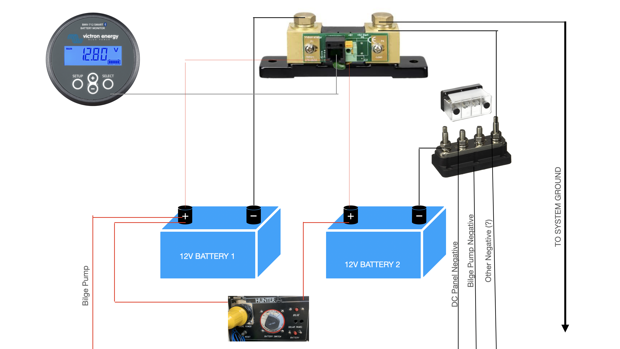
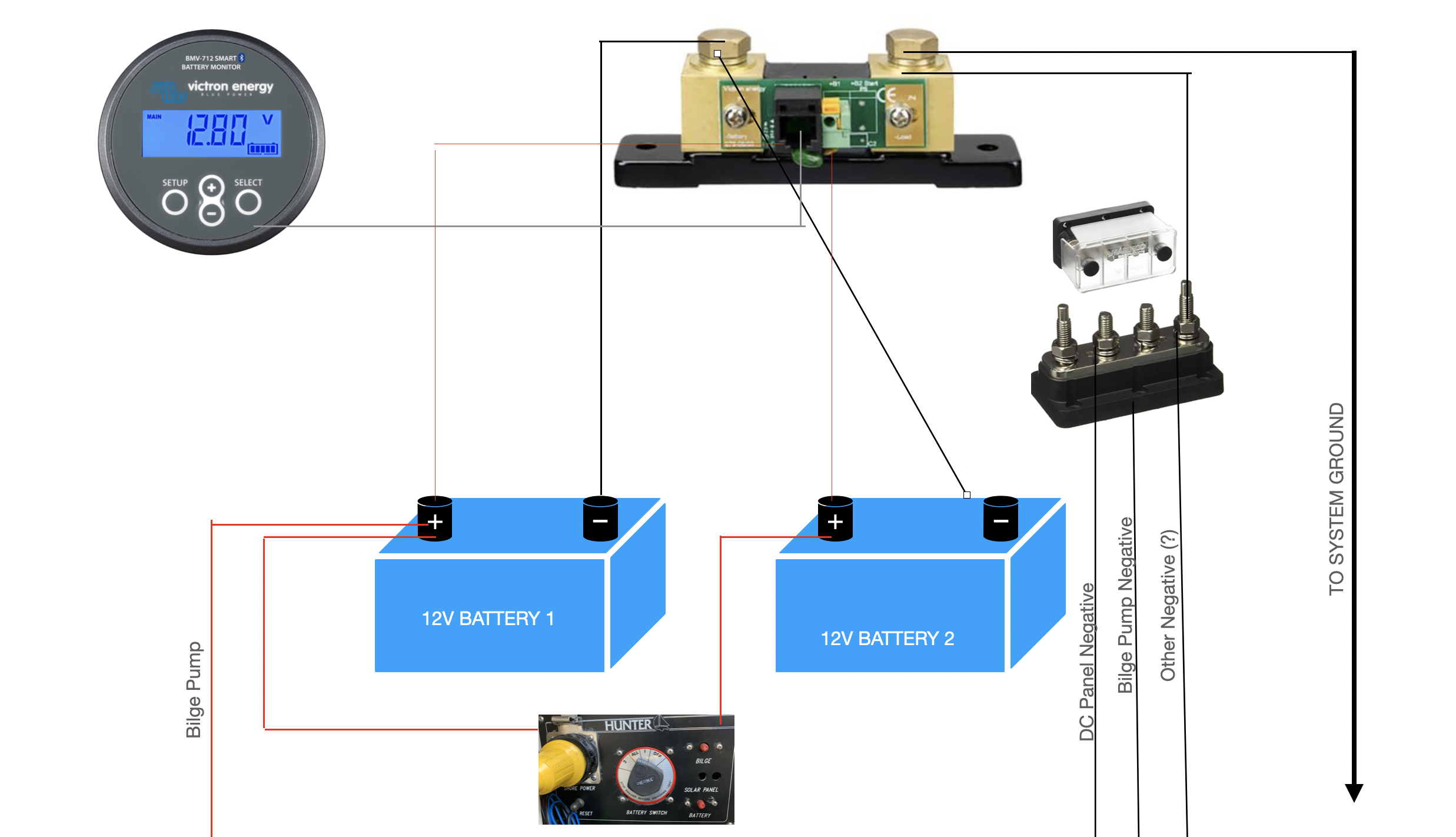
I have a BMV 712, and right now there are just too many (5) negative wires attached to the Shunt, i can't tighten the nut with the lock washer. I was thinking of adding a bus bar (Marinco 500a, no fuses) for the negative wires, and running that to the shunt. Does the wiring in this diagram make sense to do that? The negative wires are different sizes and lengths (1AWG, 8 AWG, 12 AWG), does that matter? And does it matter which stud on the bus bar the negative wires are connected to? Meaning does the last stud need the wire going to the shunt?


Or do i need the bus bar at all, and i could just distribute the negative wires across both posts of the Shunt? Right now, i had Battery 1 negative going to the left side of the shunt, and 5 other negative wires going to the right side (negative from battery 2, negative from bilge, negative from dc panel, another negative and then the wire to the ground).


Thank you for any help!


battery-wiring-diagram.png

SmartShunt
1 comment
2 |3000

Up to 8 attachments (including images) can be used with a maximum of 190.8 MiB each and 286.6 MiB total.

subdude22 avatar image subdude22 commented ·

@Jdsilwones @Justin Cook or anyone in this thread... please / thank you


I have a total of 5 shunt/battery monitors.... (Circles with black bar)

The 4 orange shunts are 100amp rating... the 1 blue shunt is a 500amp rating.

my intention is to have 1 shunt for each 100ah battery to measure the individual battery

then have the 5th shunt measure the overall system.

NOTE: yes all shunts are adequate for the appropriate amperages.

And I do realize that my 5th shunt won't be able to measure any power the first 4 shunts use.

but that power should be negligible.

the Yellow triangles are breakers or fuses.

Is this a valid configuration? if not, any suggestions? Thank you.

1709220509998.png


0 Likes 0 ·
1709220509998.png (123.7 KiB)
4 Answers
Justin Cook avatar image
Justin Cook answered ·

Hi @ErikDane, welcome to the Community!

Just to be clear, you're only monitoring the SOC of Battery 1, is that correct? If so, then your proposed solution looks fine, assuming that the POS wire shown going from Battery 2 to the shunt is being connected to the B2 port of the shunt PCB, for voltage monitoring only.

You definitely cannot distribute your NEGs across both posts of the shunt - the shunt is directional, so the battery you're monitoring must be connected on the "battery" side of the shunt, and all other system NEGs must be on the "loads and chargers" side of the shunt.

If you are intending to parallel-connect Batt 1 and Batt 2 to treat them as a single battery, however, you'll have to do some reconfiguring - see pages 18-19 of Wiring Unlimited for the 4 acceptable methods of parallel-wiring batteries.

1 comment
2 |3000

Up to 8 attachments (including images) can be used with a maximum of 190.8 MiB each and 286.6 MiB total.

Bob K avatar image Bob K commented ·
What software did you use to make the wiring graphic?
0 Likes 0 ·
erikdane avatar image
erikdane answered ·

Thanks Justin. I would like to monitor the SOC of Battery 2 as well if possible, without parallel connecting the two batteries. In that case, would the negative Batt 2 wire go to the "Battery" post of the shunt? Like this: batt-wiring-diagram-21.pngand yes, the POS wire from Batt 2 is going to the B2 port of the shunt.


Thank you!


1 comment
2 |3000

Up to 8 attachments (including images) can be used with a maximum of 190.8 MiB each and 286.6 MiB total.

Justin Cook avatar image Justin Cook ♦♦ commented ·

No, unfortunately that's not possible; the BMV/SmartShunt series is only capable of measuring SOC of one battery bank; if you want to measure SOC of both batteries, you must connect them in parallel so that they are one bank.

0 Likes 0 ·
nick-peck avatar image
nick-peck answered ·

the batteries in the second setup are wired in parallel, just not the way they should be.

i cant see i reason for doing this other than to have battery 2 switched off as a backup.

but yes, you need a bus bar on the output side of the bmv.

2 |3000

Up to 8 attachments (including images) can be used with a maximum of 190.8 MiB each and 286.6 MiB total.

jdsilwones avatar image
jdsilwones answered ·

2efbb845-e6a7-46cf-bedd-14a95b6bad55.jpeg
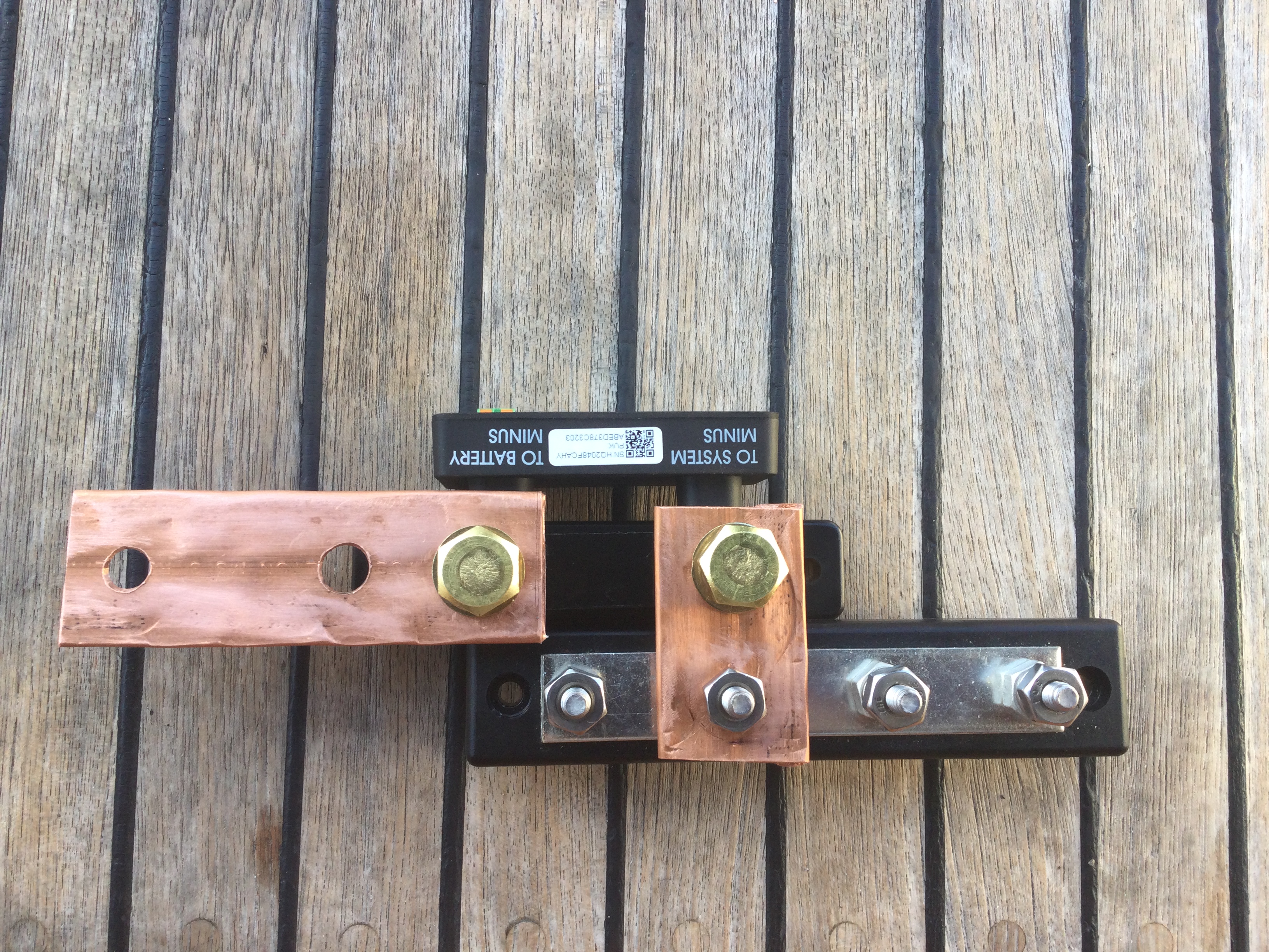
Works well in limited space. Buss bars are flattened copper pipe.


2 |3000

Up to 8 attachments (including images) can be used with a maximum of 190.8 MiB each and 286.6 MiB total.

Related Resources

Additional resources still need to be added for this topic