question

half-moon-bar-lodge avatar image
half-moon-bar-lodge asked

Wiring diagram for Quattro split phase with autotransformer?

We have an off-grid system with two 48/10000 Quattro inverter/chargers configured for split phase, with a battery bank and solar chargers. We also have a generator feeding the Quattros on AC input 1 when the batteries are low and the sun is not shining. We have a few 110 appliances that consume significant load, causing the legs to become unbalanced.

I'd like to add a 100 amp Victron autotransformer between the Quattros and the breaker panel so that we can balance the legs, especially when the generator is running.

The autotransformer manual has a wiring diagram for balancing two inverters in split phase, but it's not very specific -- it's more conceptual than "connect this to that". The manual also says "split phase output balancing may require some more attention", but never goes into more detail on how to do it. Does anyone have a more specific wiring diagram for balancing two Quattros with the 100 amp autotransformer?

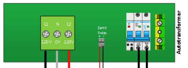
Also, the Quattros open the ground relay when the generator is running. I've wired that up to the autotransformer so that it will drive the autotransformer ground relay. However when the Quattro is powered by the generator the ground relay is opened, which I don't think I want to happen -- the autotransformer ground relay should always be closed, as far as I can tell. Does anyone have any tips for forcing the autotransfomer ground relay to always stay closed?

MultiPlus Quattro Inverter ChargerAutotransformersplit phase
2 |3000

Up to 8 attachments (including images) can be used with a maximum of 190.8 MiB each and 286.6 MiB total.

1 Answer
solardude avatar image
solardude answered ·

I will assume your generator has a neutral to ground bond, since most 120/240 generators do.

Your Quattros will still control the opening/closing of the ground relay, but will now physically happen inside the AT. The Quattro will no longer physically use its internal ground relay if configured properly.

First, you need to wire the ground relay output from the Quattro to the ground relay input on the AT. (Only needed from one Quattro) Then, you need to flip the dipswitch SW1 up (on) to enable external switching. (This part unfortunately is not covered in the manual). Also make sure ground relay is enabled in the Quattro settings. The AT ground relay will now automatically open/close when necessary.

I can’t see a situation where you would want the ground relay always closed. If your gen is running, you want the relay open. If gen is not running, relay should be closed. This is the default operation, and is Done that way to avoid more than 1 N-G bond at the same time.

8 comments
2 |3000

Up to 8 attachments (including images) can be used with a maximum of 190.8 MiB each and 286.6 MiB total.

half-moon-bar-lodge avatar image half-moon-bar-lodge commented ·

Thank you solardude! I really appreciate you taking the time to answer. I've got it wired up as you said -- one of the Quattros is controlling the ground relay on the autotransformer. It took a while to figure out to flip the dip switch... thank goodness for the community! :-)

Here's what I'm trying to figure out: when I'm running off batteries, the autotransformer balances the two legs. However when I'm running off generator (and hence the ground relay in the autotransformer is open), the legs are not balanced. Any ideas?

0 Likes 0 ·
solardude avatar image solardude half-moon-bar-lodge commented ·

The ground relay shouldn’t affect the balance. A few questions:

Where are you Getting meter readings?

Are you inverting your whole panel? Or is it a subpanel?

0 Likes 0 ·
half-moon-bar-lodge avatar image half-moon-bar-lodge solardude commented ·

I'm getting meter readings from two sources: the Quattro inverters, and the generator's control panel. The inverters indicate that the load is balanced when the generator is off. They both show the load on the generator is unbalanced when the generator is on. We are indeed inverting the whole panel -- it is wired:

  • Generators feed the inverter and a transfer switch.
  • Inverter feeds a transfer switch that allows us to feed from the inverters or directly from the generators (in case we have a malfunction in the inverters we can run directly off generator).
  • The transfer switch feeds the autotransfomer.
  • The autotransformer feeds the main panel.

Here's a conceptual diagram of the system: Lodge Wiring July 2020.pdf

On the autotransformer wiring: I'm not sure I have it wired up properly. I'm feeding the two 120v legs into the breaker, the neutral from the transfer switch (i.e. the inverters) into the yellow/green port to the right of the breaker. The output L1/L2/neutral on the left are wired into the main panel.

Any advice you can give on whether this is wired correctly would be very much appreciated. I'm pretty sure it is a grounding problem somewhere (isn't it always? :-) ).

1 Like 1 ·
half-moon-bar-lodge avatar image half-moon-bar-lodge half-moon-bar-lodge commented ·

As I was typing this up and looking at the wiring again, I realized that the problem might be that I've wired the neutral from the inverter into the ground port on the right side of the breaker in the autotransformer. To make sure I'm understanding, only the two hot legs from the inverters should be wired into the autotransformer, correct? The green/yellow port should go directly to ground?

1 Like 1 ·
solardude avatar image solardude half-moon-bar-lodge commented ·

I think you found your problem. You won’t feed the neutral to the autotransformer at all. The autotransformer labels are misleading for this application because it was originally intended for European 230V.

You will feed the AT “Line In” with the AC Out 1 Line(Hot) from inverter 1, and feed the AT “Neutral In” with the Line(Hot) from inverter 2. Tie AC out neutrals from both inverters together, they aren’t used.

The AT makes a new neutral that feeds your panel.

See this diagram if you have any issues

https://www.victronenergy.com/upload/documents/AT-4-stacked-inverter-2x120V-to-120-240V-with-2xQuattro-120V-REV-B.pdf

1 Like 1 ·
half-moon-bar-lodge avatar image half-moon-bar-lodge solardude commented ·

Thank you so much solardude! That's exactly the diagram I was looking for. I really appreciate the time you took to help!

0 Likes 0 ·
brianv avatar image brianv half-moon-bar-lodge commented ·
Did you connect the ground wire of inverters into the autotransformer at all?
0 Likes 0 ·
GARY WILLETT avatar image GARY WILLETT brianv commented ·

The primary earth (PE) connection (green wires) from all components with metallic enclosures are connected directly, or via another enclosure, to a common grounding or earthing point. This is for safety in grounded electrical systems. If a "hot" L1 or L2 conductor inadvertently energizes any metallic parts a person may touch, a fuse or circuit breaker will trip.

To answer your question, notice that each metallic enclosure in the Victron drawing linked by solardude has has an interior ground busbar to which all PE wires in/out are connected.

The green wiring from the Quattro inverters to the AutoTransformer (AT) shows a PE to the primary side of the AT. PE green wiring is required from the AT secondary ground relay to the breaker boxes. The AT has (2) terminals on the right side for any required PE conductors:

screen-shot-2021-06-19-at-45002-pm.jpg

https://www.victronenergy.com/upload/documents/Autotransformer/Victron_Energy_Autotransformer-en.pdf

If the inverter PEs are already connected to the PE busbar in another enclosure, another separate PE to the AT is not required.

0 Likes 0 ·