question

harley avatar image
harley asked

Argofet 200-2 Energize passing current to output

Hi,

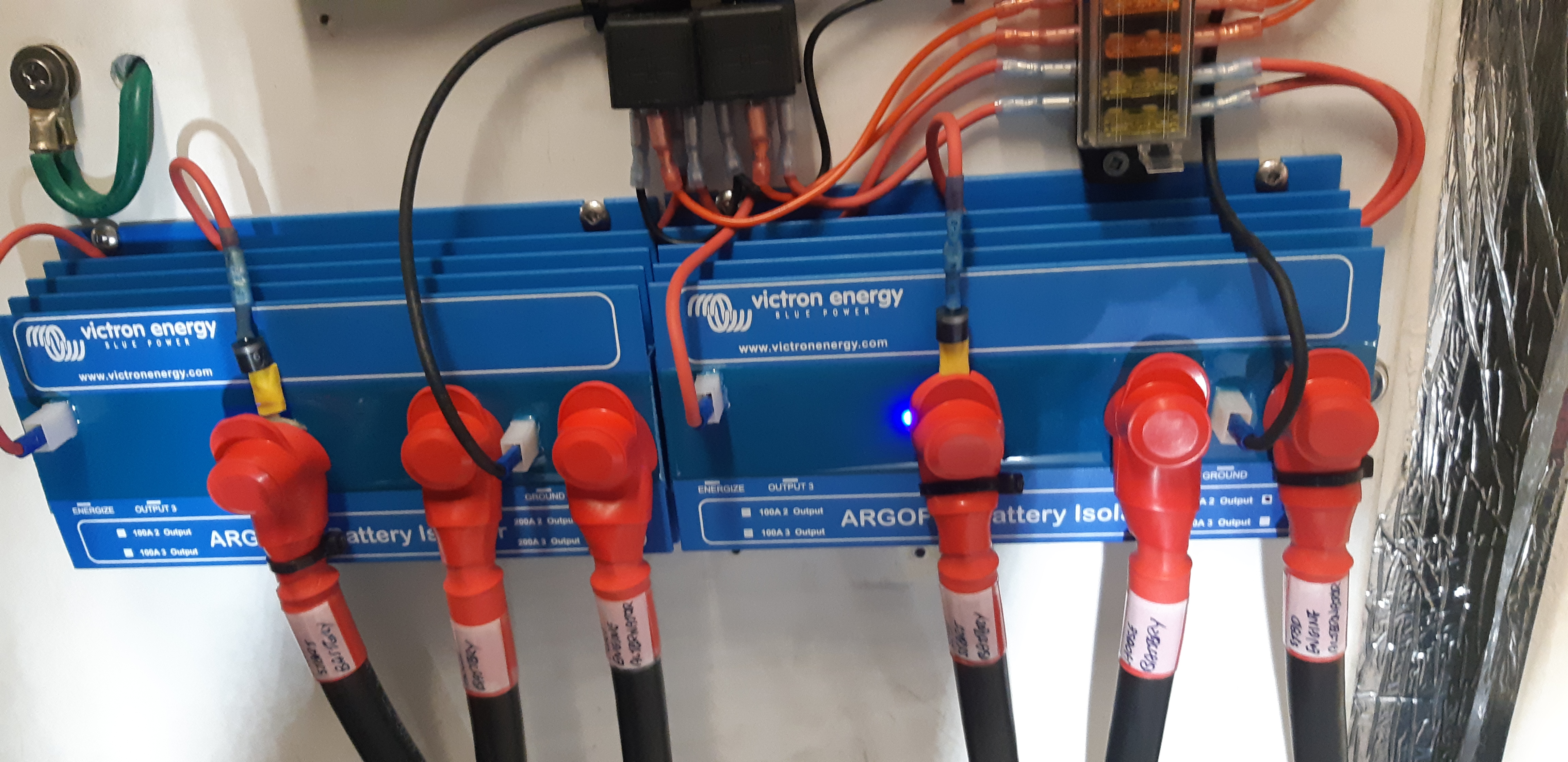
I am having an issue with some Argofets blowing 10A fuses inline with the energize inputs.

-The energize input is wired to the switched side of the starter battery isolator via 10A blade fuse.

-The alternator B+ is connected to the argofet input.

-Start battery is connected to the argofet output 1

-House battery is connected to the argofet output 2.


When the start battery isolator is on, engine not running, a current drain/load on the house bank, the energize input is supplying current to the house bank, and blowing the 10A fuse. This current path is presumably from the energize input to the input and back to the output with the lower battery voltage.

Is this expected/normal, or may i have a hardware fault?

If this were normal, should everyone be installing a 25A fuse to allow for the 20A maximum mentioned in another thread?

Thankyou,

Harley


Argo FET Diode
2 |3000

Up to 8 attachments (including images) can be used with a maximum of 190.8 MiB each and 286.6 MiB total.

8 Answers
psycho-pete avatar image
psycho-pete answered ·

Hey everyone I think that I understand what is being overlooked here.

1. The documentation and internal working of the exciter circuit and how to connect it is poor at best (I don't think they even mention a 10Amp fuse or how to wire to the starter solenoid).

2. Since there is a diode internally to limit the back current into the ignition potentially draining the battery this handles discharge issues.

3. There is a shortcoming that the designers of this circuit have not addressed regarding why there is excessive current draw blowing fuses for some.

I believe that the idea in concept is good to power the output of the voltage regulator. However when you have a battery that is dead there is a forward current path from the output of the alternator to the battery through the forward biased FETS that is causing excessive current flow because of the voltage drop.

To solve this may be different for various alternators because the voltage regulator output bias circuits will vary based on the design.

What you will need to do is disconnect all batteries or turn the switch to off.

Using a power supply you will need supply a positive voltage to the output terminal of the alternator and measure the current it requires to bring the voltage up to a few volts.

Once this current is known you need to install a series resistor in the exciter circuit to limit the current when you have dead batteries. The value will have to be such that the resistor wattage is not exceeded with a 12 volt drop across it but also will depend on the current required to bias the alternator output voltage regulator.

So let's assume the a 4 volt bias requires 50 mA. Then the resistor size using ohms law would be:

(12v-4V)=8V Resistor drop at the resistor. So, 8(V)/0.05(I)= 160 ohm (R).

Then you have to check the resistor wattage. 8Vx0.05(I)= 0.4(watts) so for this application you would need a 160 ohm 1/2 watt resistor.

This should create enough bias current to start the alternator charging without burning up any wires etc.

Note: I have not tested this, just observations and comments with no warranty.

Pete

4 comments
2 |3000

Up to 8 attachments (including images) can be used with a maximum of 190.8 MiB each and 286.6 MiB total.

mobbzy avatar image mobbzy commented ·

This problem has gone on too long, It is because Victron have failed to provide adequate installation information. a diagram of the internal arrangement and details about the limitations would allow installers to do a correct installation. I asked whether the internal fuses were auto resetting.... no answer from Victron. Clearly if they are not auto resetting then if a fault occurs you have to buy a replacement Unit.

In the meantime I have installed a 10 amp fuse and a 5 amp resettable breaker in the line from the ignition switch and the exciter terminal. This works OK but I have not tested it to blowing point in all possible modes.

Is there an alternative Device that could be used as charge splitter that would power up the B+ terminal?

0 Likes 0 ·
mobbzy avatar image mobbzy commented ·

Thanks psycho-pete. your solution is feasible.... but why couldn't Victron build something like it into the unit.

By the way, the builder of my boat (2009) connected the engine, thrusters, winch, and Inverter input to the same 3x 120 AHr battery bank. and the 12 volt domestic bits, (lighting, toilets, water pumps, heating.navionics etc to the single 110 AHr battery. But the circuit schematic showed it the other way round. Who can one trust?

0 Likes 0 ·
psycho-pete avatar image psycho-pete mobbzy commented ·

Yep, I agree it should be at least mentioned in the documentation and considered to be built in. It looks like the designers of the FET circuit overlooked this discharge condition and how it can adversely impact current flow through the exciter. This proves we are all human.

Regarding the misinformation, boat builders probably don't understand electronics all that well so some forgiveness is necessary. LOL

Good luck!

Pete


0 Likes 0 ·
psycho-pete avatar image psycho-pete commented ·

OK, so I have now tried this with an alternator on a car with two batteries and it works fine.

I wanted to clarify a couple of things in my last post.

1. Ensure that all batteries connected to the FET are charged so current doesn't flow when performing this test (raising the alternator output current and reading the charge current instead of the voltage regulator bias current).

2. The current should be very small and it was tested with the ignition on and with one battery on to see if the current increases when the voltage regulator is turned on and it did not vary.

3. The actual current that was measured was less than 1 milliamp to bias the alternator internal voltage regulator bias output (0.1 milliamp)

Assuming the current would always be small I would suggest basing a few resistors to try based simply on the wattage of the carbon resistor as follows 1\(W/(e^2))=R with a full 12 volt drop (will be less when batteries are fully charged this is worst case):

For 1/2 W, 1/(0.5 */12^2)=R, R = 288 ohms, selecting a standard value 330 ohms 1/2 W

For 1.0 W, 1/(1.0 */12^2)=R, R = 144 ohms, selecting a standard value 150 ohms 1 W

Ether of could be tried in series with the exciter power circuit. Since the current is limited the 10 amp fuse discussed could be eliminated as the voltage regulator output bias current should be minimal.

Again, it would seem logical that the alternator output current regulator output stage would consume very little current especially when the ignition is off but who knows there may be variations of regulators, I don't have that knowledge.

Also it would seem prudent for the manufacture to clarify the circuit function and add a resistor internally in series with the exciter circuit to limit over current situations when one battery is fully discharged.

There documentation could use some improvement to inform their customers of the potential overcurrent situation without a current limiting resistor.

Please respond to this post this solved your over current problems with blowing a fuses.

Note: comments with no warranty.

Best regards,

Pete

0 Likes 0 ·
dwmarine avatar image
dwmarine answered ·

Hi Harley.

Same situation here, agree with your comments.

We are having the same issue with a few of these blowing a 20 amp fuse.

Our local Victron dealer has heard of this issue, but does not have a solution.

I could not measure any appreciable current through the energise circuit with full batteries.

I have fitted a 10 amp diode in the supply to the energise circuit to try and see what will happen.

Will let you know if that changes anything.

Darren


1 comment
2 |3000

Up to 8 attachments (including images) can be used with a maximum of 190.8 MiB each and 286.6 MiB total.

yachtinst avatar image yachtinst commented ·

Hi Dwmarine, and the rest in this thread.
Any update on your two yachts with useless charging systems?
Just about to install my first Argofet. Have a relay with built-in 15A diode to hookup from the Ignition key > fuse > Relay > Energize.

Any other updates in 2021 on the wiring issues of the Energize on Argofet's ?


Cheers
Fredrik

0 Likes 0 ·
mobbzy avatar image
mobbzy answered ·

I am having same problem. I recently had to change the alternator (Nanni 5280 HE, 110 amp), and could not get one same as that fitted which did not need the excite terminal connected on the ARgoFEt. How I noticed was having fitted the new alternator, and connected the excite terminal on ArgoFet to the ignition Aux swtich. When I switched the ignition switch on, before starting engine, I was surprised as my house distribution panel lit up even though the battery was not connected. I put ammeter on the wire and found that there was no limit to the current going through. (I stopped when the load got to 20 amps so an not to set fire to the wire). Clearly if B+ is livened up in this way, and the excite voltage is not isolated from it by some sort of relay inside, then the voltage can make its way through to the outputs.

All is well if I connect the house battery and the when alternator is charging.

So clearly there is a path from the excite terminal through the "diode" to the output terminals.

I wanted to know what Victron mean when they say that the excite input is current limited??

It has been suggested to put a 5amp breaker and a 10 amp fuse and a diode in the line from the ignition switch. First to protect the line, and second to prevent reverse flow which could prevent me from switching the engine off..However, I need to do more analysis of the whole set up on my boat, (which is as built and only 10years old) before setting on a solution.

Surely something wrong with the ArgoFET if it does not limit what comes into the excite terminal.


2 |3000

Up to 8 attachments (including images) can be used with a maximum of 190.8 MiB each and 286.6 MiB total.

dwmarine avatar image
dwmarine answered ·

One of our two NZ Victron distributors had a meeting with Victron Energy today.

This subject was noted and questions asked.

I have not received any reply yet.

2 |3000

Up to 8 attachments (including images) can be used with a maximum of 190.8 MiB each and 286.6 MiB total.

mobbzy avatar image
mobbzy answered ·

It seems logical that if current can flow from the excite terminal to the outputs then if house battery is lower voltage than the engine battery, you will get flow of current from, engine battery, via ignition switch, via the excite terminal and then onto the house battery or to house loads,

potentially if not fused something along the line will blow, and that could be the supply to the Instrument panel ignition switch,

Victrons installation instructions are woefully inadequate, they do not warn that the excite line MUST be protected, either by fuse ot breaker. Perhaps even such current could blow something inside the ARGOFET.

My dealer suggested installing a relay at the argofet to allow connection between output 1 (engine battery) and the excite terminal. activated by line from ignition switch. seems this would work, but still needs to be fused/protected. I was thinking to do this but also include a resettable 5 amp breaker along with 10 amp slow fuse and possibly a diode if it turns out that current can reverse out of excite terminal. line from ignition switch to have fuse as well.

2 |3000

Up to 8 attachments (including images) can be used with a maximum of 190.8 MiB each and 286.6 MiB total.

Johannes Boonstra (Victron Energy Staff) avatar image
Johannes Boonstra (Victron Energy Staff) answered ·

Hello Harley,

The energize circuitry is quite simple. Its an electronic fuse (10A) in serial connection with a diode forwarded to the input. This fuse can supply more then 10A temperately but when the fuse heats up the current is limited.

The way it needs to be used is dat the energize gets its power from the starter battery (so when the starter battery is switch OFF there cannot be power on the energize input!!!) through the ignition switch. So as soon the engine is started the energize circuit bring the starter battery voltage to the B+ input. Current on the energize whilst the starter battery is switched of means there is an installation fault made! Beside this the neutral is also internally fused with a 2A fuse to protect internal components. PS as a general note; an Argofet should not be paralleld on the same battery and power by different alternators. Due to the fact the alternators arent symmetrical it can occur that the splitter gets overheated from switching its input on/off.

1 comment
2 |3000

Up to 8 attachments (including images) can be used with a maximum of 190.8 MiB each and 286.6 MiB total.

mobbzy avatar image mobbzy commented ·

Are the 10 amp and 2 amp internal fuses auto resetting?

0 Likes 0 ·
mobbzy avatar image
mobbzy answered ·

Johannes.

Thanks for the info that there are internal fuses in the excite system. and a diode to prevent backflow to the ignition switch. Are the 10 amp and 2 amp fuses you mention auto resetting.?

Is there a bench test protocol that can be used, or would we have to send suspect argofet back to you for testing?

It would be useful if that information was included in the installation information.

2 |3000

Up to 8 attachments (including images) can be used with a maximum of 190.8 MiB each and 286.6 MiB total.

dwmarine avatar image
dwmarine answered ·

Hi Johannes.

Yes the energise circuitry may be quite simple, but it doesnt work!

Look at all the posts on this.

Currently I have two large boats with useless charging systems, which are wired exactly as per the manual.

My local Victron Dealer and Tech have been told about this issue and queried more than 12 times in the last 7 months. Still awaiting a reply.

May I politely suggest that you set foot outside of your office and investigate the real world issues these components have, then clearly explain how you will expect to fix the "quite simple" energise circuitry so it actually works in real life.

Darren Webber

DW Marine Ltd

1 comment
2 |3000

Up to 8 attachments (including images) can be used with a maximum of 190.8 MiB each and 286.6 MiB total.

mobbzy avatar image mobbzy commented ·

My boat originally (2009) had a self energising alternator(which did not need excite terminal connected. The problems with argofet only arose after the alternator failed (2020). The new alternator supplied by nanni dealer, needed the B+ powered up, so we had to connect the argofet energise input. When I did this I found the feed through problem purely by accident because I switched on the engine battery isolator, but not the domestic battery isolator. When I turned ignition switch to ON. the domestic services came to life. THe problem is highlighted when engine not running but ignition switch is in first ON position, or HEAT position, Once engine running all is OK because it's pushing equal voltage to both batteries. So I put fuses in the excite line just in case until Victron can give a Verified answer. The uncertainty the problem has highlighed is the main issue here.

I've no way of testing the Argofet to see if it is within specifications, or if has internal faults, permanent or intermittent, except by replacing with new one and comparing it's behaviour.

0 Likes 0 ·