question

bergmans-trading-cc avatar image
bergmans-trading-cc asked

Multiplus II 5KVA pass through power?

Good day all

I have a question for the more experienced members here.

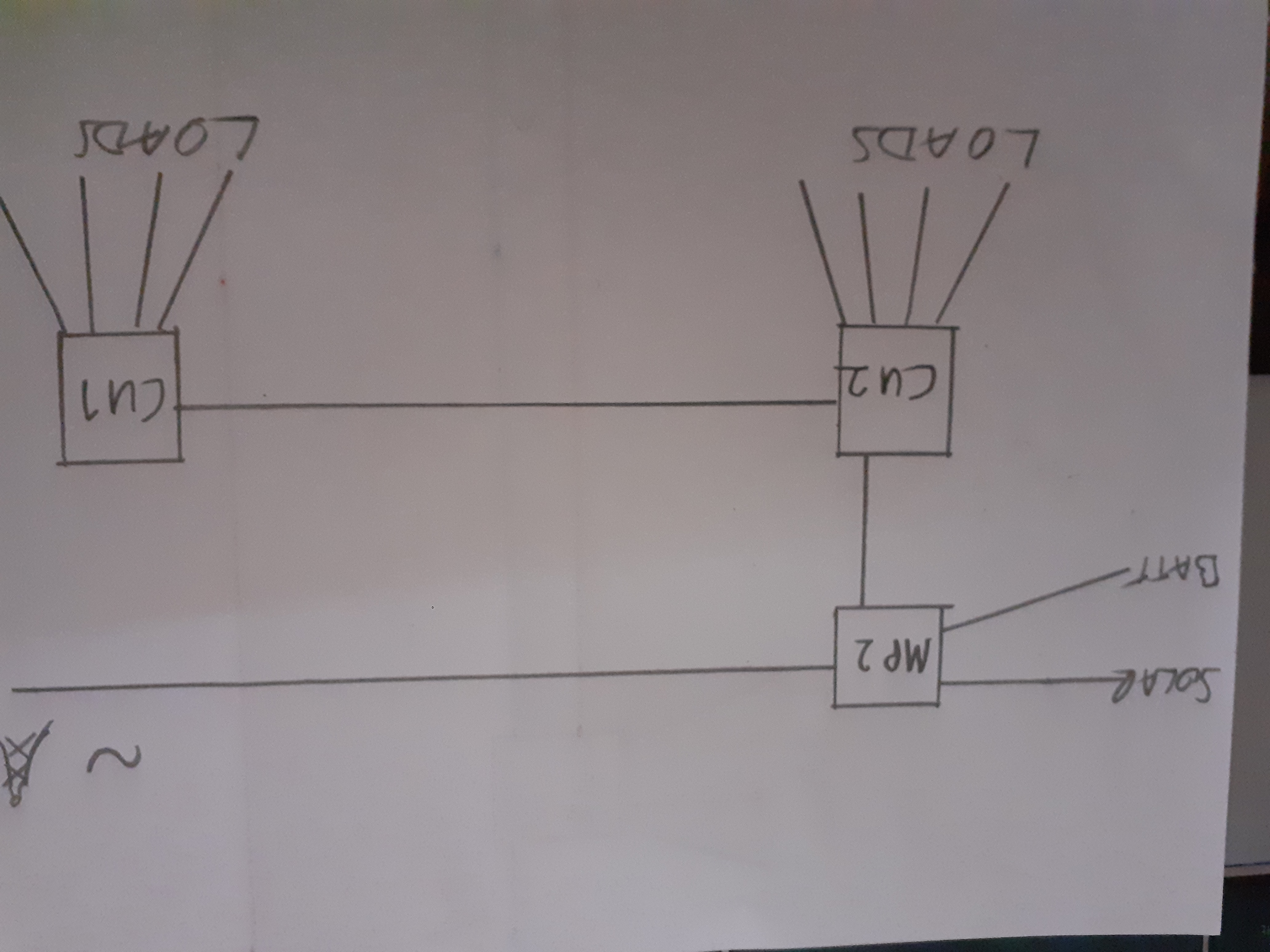
I have a Multiplus II 5KVA with a Smartsolar 250/85 charge controller, 12 x CS350 watt panels and a 10kwh lithium bank.

The house is equipped with a gas geiser and stove.

Power consumption was measured with logging device for about a week and peaked at 4.9kw with an average of 3.4kw throughout.

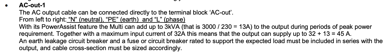
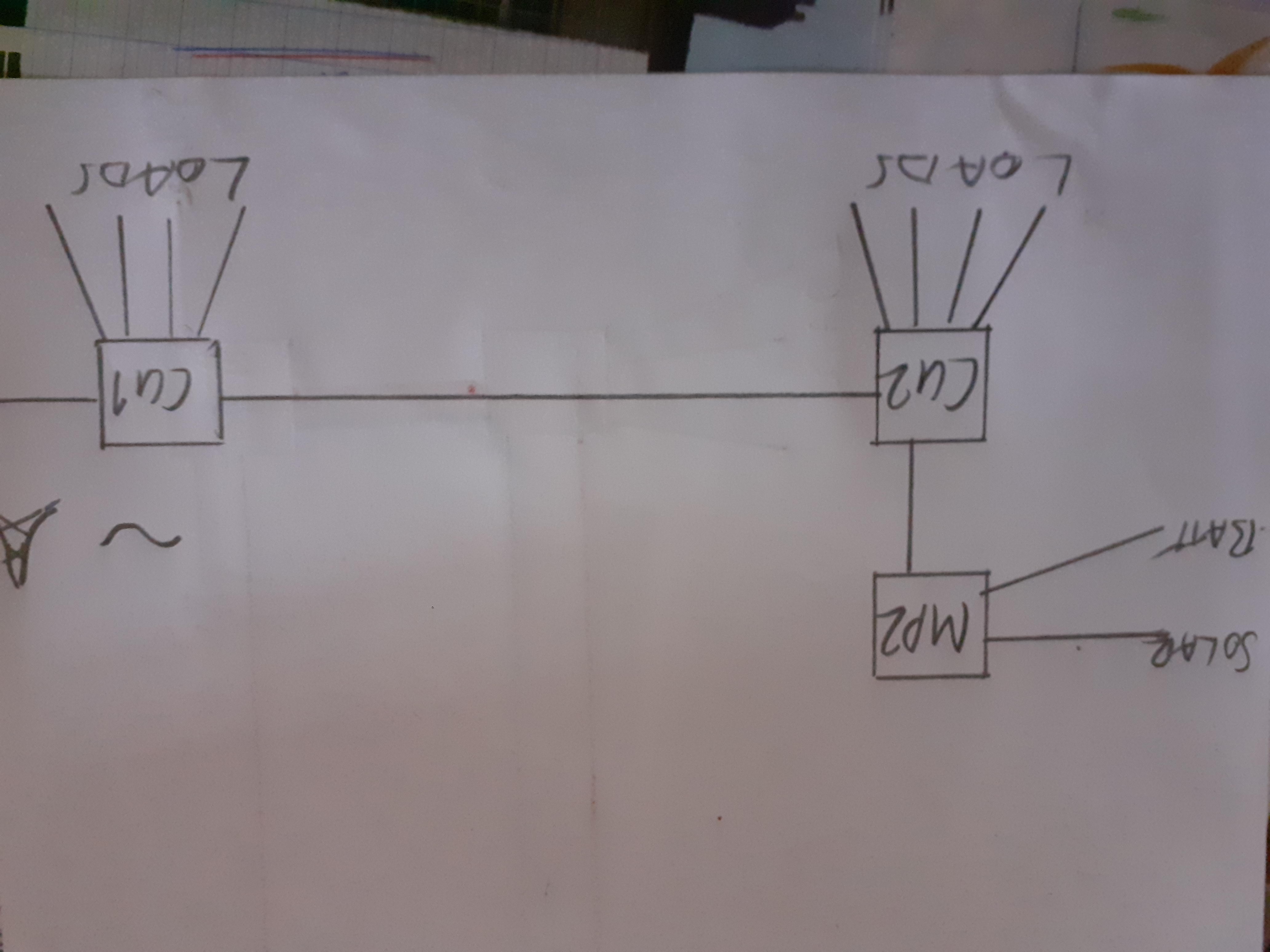
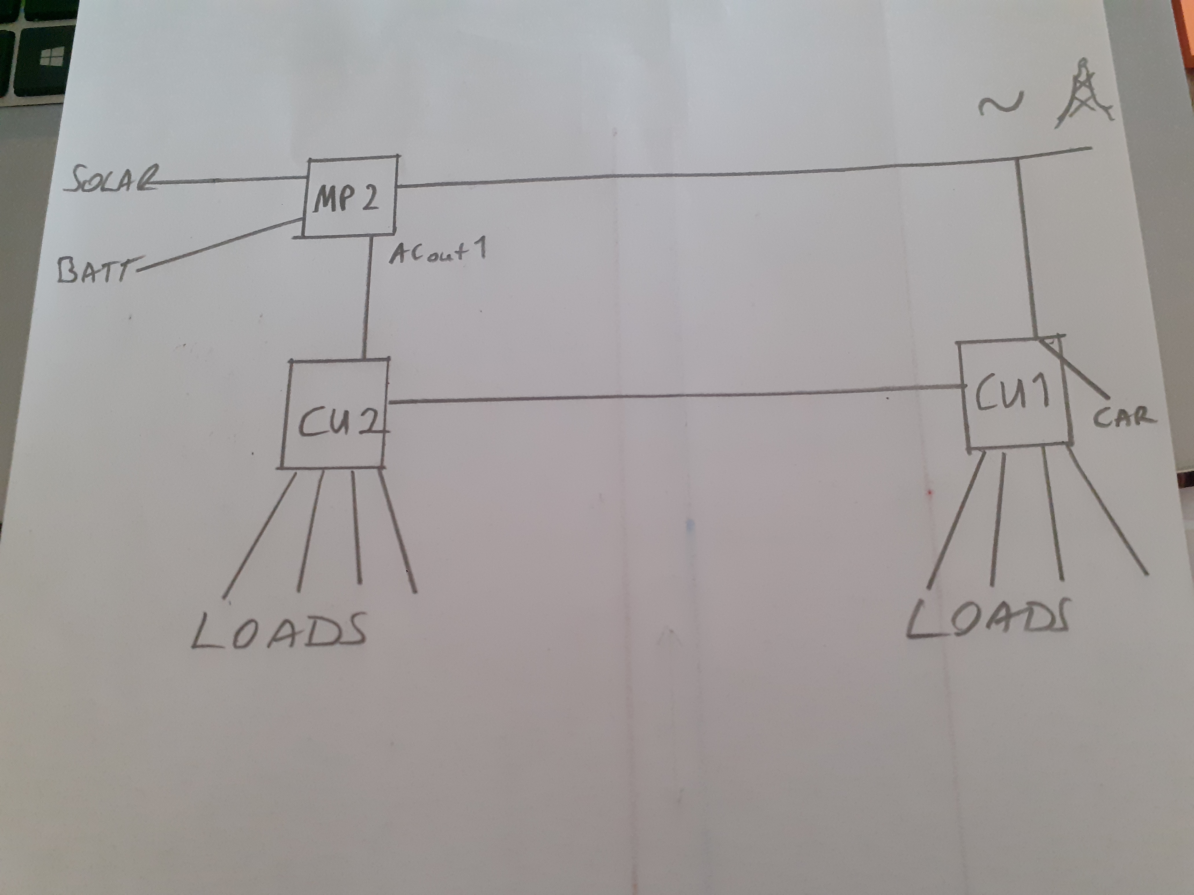
My question is can I feed the main AC from the grid through the Multipus with the main DB box connected to AC output 1 ( no break ) on the Multi.

Given that I will setup the ESS system to keep batteries charged and only use battery during load shedding.

The aim is to gain as much savings possible from PV and not have the hassle of splitting loads between AC outputs on the Multi.

I hope this makes sense?


Your input will be greatly valued.

Multiplus-IIESSinput current
1 comment
2 |3000

Up to 8 attachments (including images) can be used with a maximum of 190.8 MiB each and 286.6 MiB total.

Alexandra avatar image Alexandra ♦ commented ·

@Bergmans Trading cc

I have seen a setup like this a 5kva running a house main DB from it's main output breaker. Running ESS. Works well if the users are good stewards.

The owners just need to juggle their loads manually to make sure there is no overloading of the system. 4000w as the datasheet says with some sympathy when there is temperature derating.

You can set a limit in the GX device to the 4000W and then was will pull from the grid more if the kids go over but this will not work during a power cut so they would still need to be aware of their loads. Also stress things like after a power cut the transfer capability also includes the Amperage drawn to recharge the batteries.

0 Likes 0 ·
6 Answers
Matthias Lange - DE avatar image
Matthias Lange - DE answered ·

I think all informations you need are in the datasheet.

https://www.victronenergy.com/inverters-chargers/multiplus-ii#datasheets


mpiidata.png (88.0 KiB)
2 |3000

Up to 8 attachments (including images) can be used with a maximum of 190.8 MiB each and 286.6 MiB total.

Warwick Bruce Chapman avatar image
Warwick Bruce Chapman answered ·

50A Maximum AC input current at 230V = about 11500VA plus 5000VA from the inverter if PowerAssist is enabled. That means means you could - in theory - support loads of 16500VA on the output.


Eg. In the case of the MultiPlus II 3000VA:


1596482202685.png (57.9 KiB)
2 |3000

Up to 8 attachments (including images) can be used with a maximum of 190.8 MiB each and 286.6 MiB total.

usernamepasswordbs avatar image
usernamepasswordbs answered ·

I am also looking for some further information on this before I change my wiring.

I have been running since install with the ACin only connected (with a grid meter installed at the incoming grid supply point), no connection on ACout. All is working ok.

The Grid connection is into a Consumer unit/Distribution board in the house (CU1) which supplies house loads, then via a 6mm2 cable to another consumer unit (CU2) in an outbuilding about 25m away from the house which also supplies some loads. The MPII 48/5000 is in this outbuilding connected to CU2. I have just installed a 10mm cable between the two CUs so my questions are around whether I should run the grid supply out to the outbuilding (25m - 10mm2 cable) through the MPII then supplying CU2 and also back again (25m - 6mm2 cable) to CU1 (i.e the house is disconnected from the grid, only supplied via the MPII 25 metres away) or just replace the 6mm2 cable between CUs with 10mm2 cable and carry on with both CUs and the MPII in parallel and leave the 6mm2 cable redundant? This means of course no leccy in case of grid failure which would be a shame.

1 comment
2 |3000

Up to 8 attachments (including images) can be used with a maximum of 190.8 MiB each and 286.6 MiB total.

usernamepasswordbs avatar image usernamepasswordbs commented ·

Maybe a picture will make sense of my question.

This is how it is now:

20230410-095501.jpg


This is how I think i want to connect using ACout1:

20230410-095449.jpg

This way all current will pass through the MPII and I don't fully understand the way current passes through it. Does it do so without losses or conditions except the 50A input current limit?

I cannot find any real explanation of how this works in the Victron MP documents.

There is mention above of 16kva capability, the 11kva grid input plus 5kva inverter output if power assist is enabled (although in my manual it says 3kva power assist, there is no distinction between models).

Anyway, is there any reason not to run everything through the MP2 including a 7kw car charger and 4kw pizza oven?

0 Likes 0 ·
gazza avatar image
gazza answered ·

The diagram from the ESS manual depicts a straight forward switch (relay). When AC IN (grid... ) is available then AC In is transferred to AC OUT 1
screenshot-2023-04-10-at-094448.png


5 comments
2 |3000

Up to 8 attachments (including images) can be used with a maximum of 190.8 MiB each and 286.6 MiB total.

usernamepasswordbs avatar image usernamepasswordbs commented ·

Thanks, it's just a relay then. Or actually two in series, going by the diagram. Or are they some sort of MOSFETs?

0 Likes 0 ·
gazza avatar image gazza usernamepasswordbs commented ·
I believe it is just a relay? I also believe there are 2 switches in series to satisfy DNO requirements regarding disconnection in the event of grid failure.
0 Likes 0 ·
usernamepasswordbs avatar image usernamepasswordbs gazza commented ·
Cool, so there shouldn't really be any losses then.

Where do you get the information from though? I have searched a fair bit and not found it anywhere.

0 Likes 0 ·
gazza avatar image gazza usernamepasswordbs commented ·
Mainly from looking at the Victron flow diagrams and from what I have learnt from other peoples experience/discussion on this forum. I have never actually seen the PCB/internal wiring of the Multiplus but it would not be difficult to take the metal cover off and take a closer look if necessary?
0 Likes 0 ·
gazza avatar image gazza usernamepasswordbs commented ·
0 Likes 0 ·
rvicev avatar image
rvicev answered ·

In any case you definitely would not want to do this on 6 mm2 .....

Note that you have already introduced a tension loss on the 25 meter / 10 mm2 grid extension from the house to the outbuilding.

Next, if you want to feed back a theoretical maximum of 16500 VA continuous (>70A @ 230 VAC) over 25 meters to the house, this would require @ 3% tension loss (additional) : 10 mm2 (@ 2% this would become 16 mm2 and @ 1% this would be 25 mm2, assuming the use of copper cable). Cable section calculators can be found on the internet.

For the rest : it all depends on your loads and where they are (CU1 / CU2) and how much you use simultaneously .....).

Also note that 5 kVA is continuous power .... the peak power of the 5kVA MP-II is 9000 W ....

2 comments
2 |3000

Up to 8 attachments (including images) can be used with a maximum of 190.8 MiB each and 286.6 MiB total.

usernamepasswordbs avatar image usernamepasswordbs commented ·

I am only thinking about it now that I have the 10mm2 installed and 3% would be within tolerances and a 16kva moment would be never although the 50m round trip for house loads is still a waste even at lower power.

The current installation on 6mm2 is only carrying inverter power back to the house and would only be for house loads if I run everything through the MP.

Here is an amended layout which would maybe be better:

20230410-123723.jpg

Here the car charger is fed from AC before the MP.

This way the 6mm return to the house would only supply normal household loads, no car, no electric shower either.

0 Likes 0 ·
rvicev avatar image rvicev usernamepasswordbs commented ·

So if the grid fails no car, no pizza, no shower ? Are you going to physically separate these on the switch board CU1 in the house so that they are only connected to the grid, and not to the MP-II ?

0 Likes 0 ·
usernamepasswordbs avatar image
usernamepasswordbs answered ·

No such thing as an electric shower in France, it's all mains pressure hot water, but yes, no car, no pizza. They both do the battery up in no time anyway.

So, after the main RCD on the incoming grid in CU1 I will separate the car outlet on a 32A trip and the 10mm2 cable on a 50A trip from everything else in fusebox CU1. Then the 6mm2 comes back to CU1 from the MPII to supply all other house loads.


2 |3000

Up to 8 attachments (including images) can be used with a maximum of 190.8 MiB each and 286.6 MiB total.