question

zamigill avatar image
zamigill asked

AC output issue Multiplus 12/2000

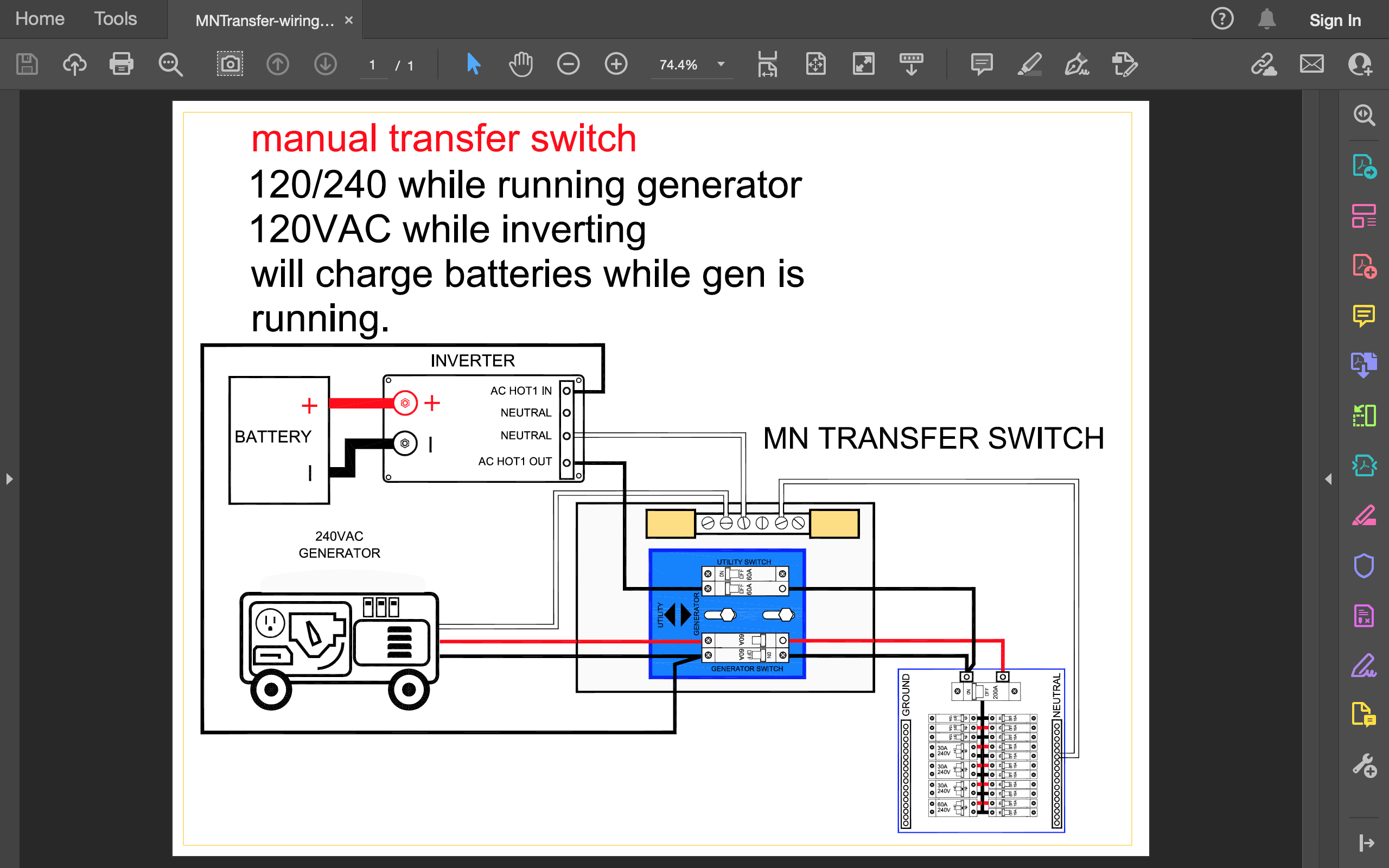
Hi, I seem to be experiencing an issue on the AC side of my Victron Multiplus 12/2000 Inverter. It utilizes 400W of Solar PV, the MPPT 100/30 Charge Controller, a 200AH lithium battery bank and a lot of wiring components in a frustratingly confined compartment. I have combed through the system referencing the design from Explorist.Life (https://www.explorist.life/200-amp-hour-400-watt-camper-van-solar-kit/) I used, have tested for shorts, faults, polarity, circuit continuity, OCPD integrity, tourques, voltages (34VDC from solar, 14.4 between battery terminals and busses, 120VAC from distribution panel) and nothing seems out of sorts to me. The DC side of the system appears to work fine, but I am stumped as to what could be causing the inverter to throw an error every time I turn it on, and why it will not produce any AC output to distribution panel.

Has anyone experienced a similar problem? Have I overlooked something obvious? Any advice appreciated.

Here is a short video I made for an overview of the problem: https://www.youtube.com/watch?v=AHOKcGVW-BM&feature=youtu.be


MultiPlus Quattro Inverter ChargerAC PV Coupling
2 |3000

Up to 8 attachments (including images) can be used with a maximum of 190.8 MiB each and 286.6 MiB total.

6 Answers
ejrossouw avatar image
ejrossouw answered ·

Hello @zamigill I'd personally remove it from the RV and just connect the ACIN (120VAC) from what I understand and see if it will turn it on like that. If not, a trip to the dealer will be in order.

2 comments
2 |3000

Up to 8 attachments (including images) can be used with a maximum of 190.8 MiB each and 286.6 MiB total.

zamigill avatar image zamigill commented ·

Do you mean, disconnect everything, batteries et al, and see if the inverter will turn on with just AC In connected with shore power on?

0 Likes 0 ·
ejrossouw avatar image ejrossouw zamigill commented ·

Yes, but use e.g. a shore extension lead bypassing the RV internals altogether.

0 Likes 0 ·
solardude avatar image
solardude answered ·

What is the larger Red wire going to a breaker in your load center? And the larger white wire going to the neutral bus?

3 comments
2 |3000

Up to 8 attachments (including images) can be used with a maximum of 190.8 MiB each and 286.6 MiB total.

zamigill avatar image zamigill commented ·

It's Line (taped red so I could ID it), Neutral (taped white) and Ground (green) from the AC Output of the Inverter. I have it transitioning from NM cable, which is what you see running into the inverter.

0 Likes 0 ·
solardude avatar image solardude zamigill commented ·

Lots of questions...

Ok, so you have what looks like 12/3 romex coming out of the AC out on the inverter. Where and why does it transition to what looks like 8awg going to the neutral bus and the bottom breaker?

You also have those cables labeled “solar inverter”, do you have an AC ouput solar inverter? I only saw the MPPT which would charge the battery from solar.

Are you running the inverter loads thru a sub panel or are you powering the entire load center from the inverter?

Where does shore power connect? Directly to inverter?

Either way, the AC out Line from inverter shouldn’t be going thru a breaker in the load center. It should either be wired to the main input lug, or powering a separate sub panel.

0 Likes 0 ·
zamigill avatar image zamigill solardude commented ·

First of all, thank you thank you thank you for the feedback and help.

Q1: It's 10/3 romex and it transitions with buchanan crimps to #6 because the plans I used specified using 6/3 for the inverter AC output, and only after I ran it did I realize that it was wildly oversized. And rather than repull that cable, I decided to transition to NM to get it the rest of the way to the inverter from my junction box.

Q2: This is both an AC in and AC output enabled inverter. The charge controller feeds the battery bank (2- 100AH LiFePO4 batteries paralleled), the batteries feed the inverter, and the inverter is supposed to feed the distribution panel.

Q3: I'm trying to power the entire load center with the inverter.

Q4: Shore power connects onto the 30A breaker in the distribution panel, not directly to the inverter. Is this also where I should be landing my AC output circuit, directly on the main breaker?

Q5: Got it, that seems to be where I'm going wrong. Can you help me understand why I can't or shouldn't be landing the AC out on its own breaker in the distribution panel?

Thanks again!

0 Likes 0 ·
solardude avatar image
solardude answered ·

First thing I would do is connect battery to inverter, with no AC in or AC out connections. Meter the AC out and make sure you have 120V.

From there, if that is correct, we need to sort out the rest of the wiring.

2 |3000

Up to 8 attachments (including images) can be used with a maximum of 190.8 MiB each and 286.6 MiB total.

Kevin Windrem avatar image
Kevin Windrem answered ·

I agree with solardude. This does appear to be an unsafe/dangerous situation.

It appears that if you have the shore power breaker and the inverter breaker on at the same time that you will be back feeding AC from the breaker panel into the inverter AC OUTPUT. This will likely damage the inverter and could be very bad (smoke, fire).

You may be preventing back feed with proper setting of breakers but it's a receipt for disaster.

The inverter needs to be fed from shore power BEFORE it enters the AC distribution panel. Then, the output of the inverter connects to the shore power input of the AC distribution panel.

The inverter also makes neutral to ground connections only when running on inverter with the AC back-feed relay open. With the unit off, you should not see any continuity between any AC connections (except PE to PE) because both the ground-neutral and back-feed relays will be open.

If you fire up the inverter with NO AC input or output connections and see 120 volts at the output then you may be OK. But if there's no AC voltage or your get an alarm of some kind, then the inverter has probably been damaged.

1 comment
2 |3000

Up to 8 attachments (including images) can be used with a maximum of 190.8 MiB each and 286.6 MiB total.

zamigill avatar image zamigill commented ·

Thanks for the feedback and clarification!

I see your points and recognize why and how I have incorrectly tied the inverter into the distribution panel. Now I'll see if I can correct this and verify that the inverter is still in good working order. Fingers crossed.

0 Likes 0 ·
solardude avatar image
solardude answered ·

Q1. 10/3 is plenty of wire for 3000W inverter. I would re run it with direct 10/3 to avoid problems later.

Q5. You can’t land 2 sources of power to the same distribution block. It is unsafe and will backfeed. If you haven’t already killed the inverter, it will certainly kill it if you try it again wired as is.

The proper way to power the entire load center is this:

Shore power feeds AC IN on inverter. Inverter AC OUT feeds load center(main input LUG, do not connect to a breaker).

You should also have a shore power breaker onboard within 6 feet of where it comes into the trailer, or less if possible. The pedestal has a breaker, but I would never rely on a pedestal breaker personally. Those things are sketchy at best.

There are a ton of Victron diagrams on their site showing how to properly connect it. I’m not sure where you got the idea of feeding both shore power and inverter to breakers, but from here forward I would disregard any website or person that told you to do so. That is as dangerous of a scenario as I have seen.


2 comments
2 |3000

Up to 8 attachments (including images) can be used with a maximum of 190.8 MiB each and 286.6 MiB total.

Kevin Windrem avatar image Kevin Windrem commented ·

Yes, what solardude says!

Actually, the AC distribution panel in your RV has a main breaker and there are no lugs to make a direct buss connection. The main breaker is the one at the top of the panel - the 30 amp with the metal bracket that prevents the breaker from being removed from the bus. The output of the Multi should connect to this breaker.

The breaker ahead of the Multi input that solardude discusses will need to be added. There are lots of options including a standard electrical disconnect box with a single 30 amp breaker. But these boxes with breakers tend to be on the large side but can be mounted out of the way.

Paneltronics, Blue Sea (and others) also sell an AC Main breaker panel:

https://www.paneltronics.com/Electrical_Panels.asp?op=ProductSearch&item=9982316B

https://www.bluesea.com/products/8077/AC_Main_30A

These are nice because they are more compact and indicate a hot-neutral reversal. There are also versions that trip when a hot-neutral reversal condition exists.

0 Likes 0 ·
zamigill avatar image zamigill commented ·

Thank you very much for the clarification! Very helpful

0 Likes 0 ·
tmartin000 avatar image
tmartin000 answered ·

I just added a second breaker in that distribution panel, one 30a for the new input from the Multi. That gives me 2- 30a breakers, both are on all the time.... Upstream of that, I added a manual transfer switch that will ONLY allow for ONE HOT breaker. Either SHORE or MULTI. Here is what I used.....I have had electronic transfer switches fail and I wanted one that was idiot-proof.

https://www.solar-electric.com/midnite-solar-60-amp-240-volt-dual-ac-manual-transfer-switch.html

screen-shot-2021-10-25-at-63920-am.png


2 |3000

Up to 8 attachments (including images) can be used with a maximum of 190.8 MiB each and 286.6 MiB total.