question

hhaley avatar image
hhaley asked

SmartShunt 500A/50mV always shows negative current

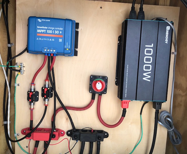
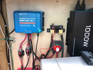
I installed a SmartShunt 500A/50mV in my system which consists of a Victron SmartSolar MPPT 100/30 charge controller and three OutBack 12V 200PLC batteries connected in parallel. Also installed in the system is a Victron Battery Sense. All three Victron products are connected via the Bluetooth network and are sharing data.

Because of the number of connections, all the positives are connected to a red 4 terminal Fastronix distribution block and all the negatives are connected to a black 4 terminal Fastronix distribution block.

The only load is a Renogy 1000W 12V inverter. Like the batteries, the inverter connections are also connected to the positive and negative distribution blocks.

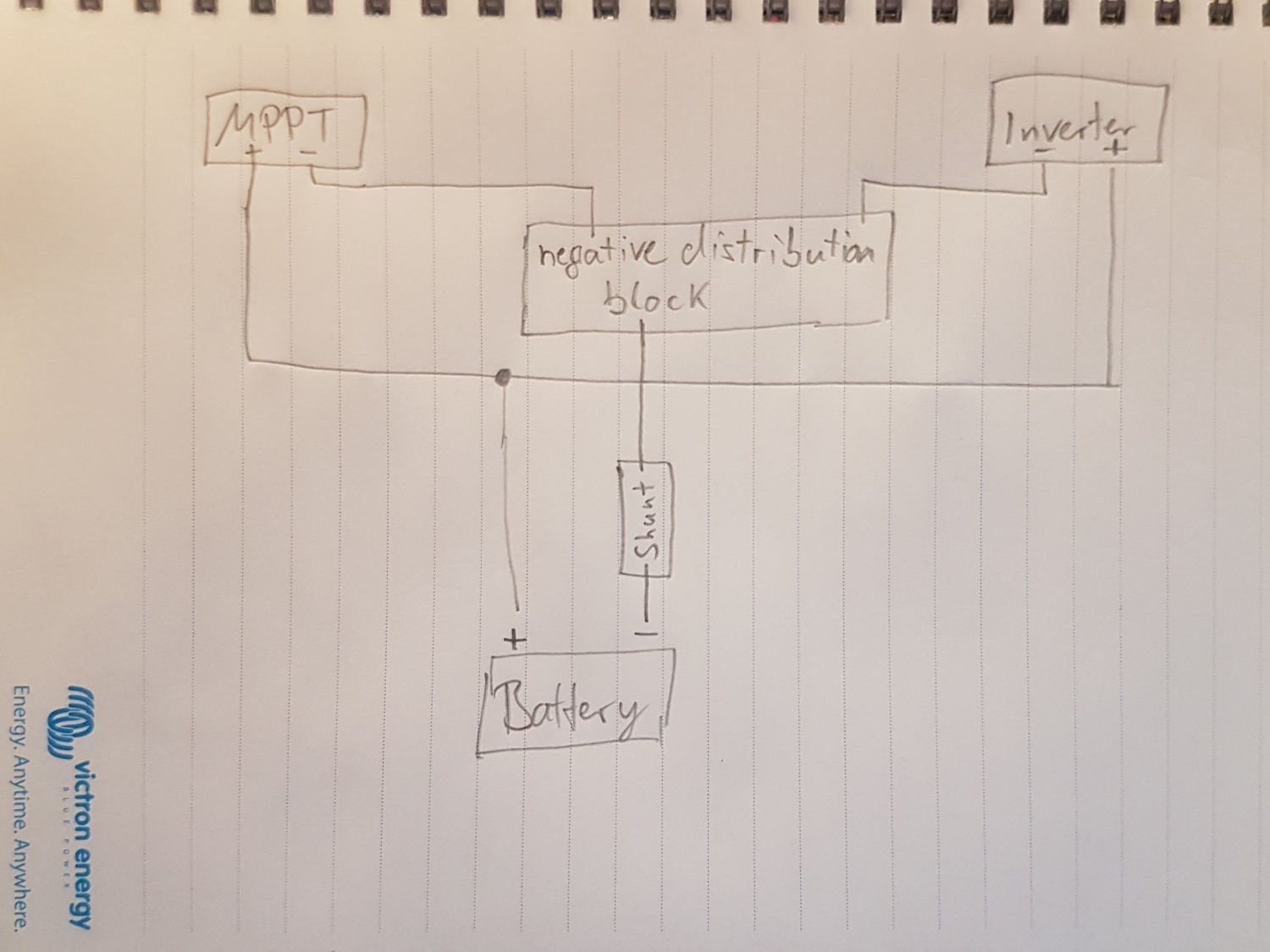
The smartshunt was installed directly above the negative distribution block. The negative lead to the inverter was disconnected and connected to the Load Minus Connection. A new cable was used and connected to the Battery Minus Connection of the smartshunt and to the negative distribution block. Essentially, the SmartShunt was installed in the middle of the negative cable going from the negative distribution block and the negative terminal of the inverter.

The power wire of the smartshunt is connected to the positive distribution block. I know the quickstart guide said to connect the power wire directly to the positive terminal of the battery but the guide didn’t cover the situation of three batteries in parallel. Which battery do you choose?

The smartshunt always is showing a negative current. It doesn’t matter what state the charge controller is in (bulk, absorption or float).

My gut tells me that something is not right and that I should see a positive current going into the battery bank at least during the bulk or absorption phase.

Any help would be appreciated.

BMV Battery Monitor
2 |3000

Up to 8 attachments (including images) can be used with a maximum of 190.8 MiB each and 286.6 MiB total.

5 Answers
Matthias Lange - DE avatar image
Matthias Lange - DE answered ·

Can you give us some pictures or a wiring diagram?

The only cable connected to the battery negative is going directly to the shunt (battery only), from "LOAD minus" of the shunt to you distribution block and all negatives (DC-loads, MPPT, inverter) also to the distribution block.
https://www.victronenergy.com/upload/documents/Quick-Install-Guide-SmartShunt-EN.pdf

2 |3000

Up to 8 attachments (including images) can be used with a maximum of 190.8 MiB each and 286.6 MiB total.

hhaley avatar image
hhaley answered ·

Above is an image before the SmartShunt was installed.


Below is an image with the SmartShunt Installed. The black cable on the most right side of the black distribution block is connect to the negative battery terminal of the smartshunt. The negative load side of the shunt is connected to the negative terminal of Renogy inverter.


1 comment
2 |3000

Up to 8 attachments (including images) can be used with a maximum of 190.8 MiB each and 286.6 MiB total.

Matthias Lange - DE avatar image Matthias Lange - DE ♦ commented ·

Wired that way is wrong and the shunt only can measure the current of the inverter.

Just take a look at the manual I linked below.

Again:
- from the negative of the battery you have to go to the "Battery minus" side of the shunt
- from the "Load minus" side of the shunt you go to your negative distribution block
- and all the negatives of the inverter, the MPPT and DC-loads are also connected to the negative distribution block

0 Likes 0 ·
hhaley avatar image
hhaley answered ·

Are you saying to put the smart shunt BETWEEN the battery negative terminal of the MPPT charge controller AND the negative distribution block?

6 comments
2 |3000

Up to 8 attachments (including images) can be used with a maximum of 190.8 MiB each and 286.6 MiB total.

Matthias Lange - DE avatar image Matthias Lange - DE ♦ commented ·

NO!

Between the battery negative and the negative distribution block!

0 Likes 0 ·
20200618-204909.jpg (781.6 KiB)
hhaley avatar image hhaley Matthias Lange - DE ♦ commented ·

Ok. I think I kind of get it but I have 3 12v batteries in parallel. I would have to connect the negatives of all three batteries to the shunt battery negative terminal. Correct? Thanks for your patience.

0 Likes 0 ·
hhaley avatar image hhaley hhaley commented ·

Well I would like to say the third time is the charm but I think it took me four times to get it right.

It works. The power received by the batteries via the shunt matches the power the charge controller says its producing.

The wiring looks ugly. Instead of neat wiring using the distribution blocks. The wiring looks like a spiderweb with all the battery negatives going to the neg battery terminal of the shunt.

Thanks again

Harry

0 Likes 0 ·
Kevin Windrem avatar image Kevin Windrem hhaley commented ·

If you can't get all three battery cables onto the shunt battery - post, use a second bus bar to join the battery negative leads then connect the bus bar to the shunt.

0 Likes 0 ·
hhaley avatar image hhaley Kevin Windrem commented ·

Excellent Idea. I can do that easily.

One last question. If I wanted to use that 2nd voltage sensor wire, where would you recommend that I install it given I have three batteries in parallel?

0 Likes 0 ·
Kevin Windrem avatar image Kevin Windrem hhaley commented ·

A "midpoint" voltage measurement makes sense if you have batteries in series. Or you can use it to monitor the voltage of your starter battery. Failing that, there really isn't anything else to measure.

Make sure the connections from battery to bus bar are the same length so that currents will more closely balance. The voltage probe should connect to one of the battery positive terminals since any wire voltage drop will upset the Smart Shunt's voltage calculations.

Also keep the connections between battery negative and the smart shunt as short as possible, also to give the most accurate BATTERY voltage to the SOC and other calculations. Oversize these wires if necessary to minimize voltage drop.

Remember in high current circuits, treat every connection as a resistor. Keeping wiring short, minimizes but does not eliminate resistance. Your system isn't super high current but it still makes for a better system.

0 Likes 0 ·
lklmenterprises avatar image
lklmenterprises answered ·

Not sure if you got this fully sorted or not.

Don't forget all Battery leads should be identical in length, and Ideally (which it looks like you have) - is to have a Negative bus bar and Positive bus bar.

Making sure that your Shunt goes in between your Battery bank and the Negative Bus bar.

Normally with only a couple of batteryes you can connect them directly to the Shunt, and then the other side goes to the Negative Bus bar.

In the event you have too many Parallel batteries (too many lugs to fit on Shunt) - just create a 2nd Bus Bar in between it and the Batteries.

So

Batt 1 > Shunt > Bus Bar > Load(s)

Batt 2 > Shunt > Bus Bar > Load(s)

Or

Batt 1 > Bus Bar 1 > Shunt > Bus Bar 2> Load(s)

Batt 2 > Bus Bar 1 > Shunt > Bus Bar 2> Load(s)

Batt 3 > Bus Bar 1 > Shunt > Bus Bar 2 > Load(s)

Batt 4 > Bus Bar 1 > Shunt > Bus Bar 2 > Load(s)


The Whole idea is - the Shunt should be a SINGLE path for current to travel through - that is why they are normally rated so high, and include 500, 1000, 2000a etc.

2 |3000

Up to 8 attachments (including images) can be used with a maximum of 190.8 MiB each and 286.6 MiB total.

2624luis avatar image
2624luis answered ·

@HHALEY
Old post and you never confirmed if you fixed or not...
Maybe this is a dumb question/suggestion mine... Have you calibrated the shunt with zero load?

2 |3000

Up to 8 attachments (including images) can be used with a maximum of 190.8 MiB each and 286.6 MiB total.

Related Resources

Additional resources still need to be added for this topic