question

Fideri avatar image
Fideri asked

Comments on design and sizing?

Hi Everybody,

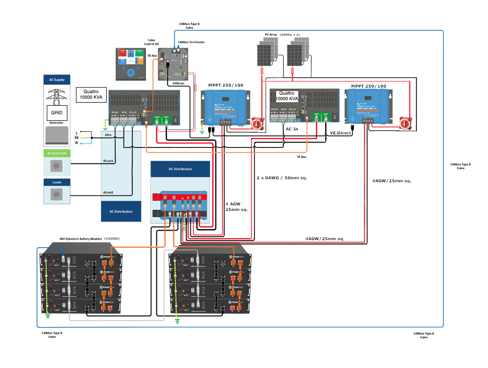
As it happens, my design is very similar to the example given by Victron in the Pylontech manual. The main differences are that I am using two MPPTs and two Quattros (instead of one MPTT and a Multiplus) and I have many PVs (up to 40 panels). So I have "stolen" the Victron schematic drawing and modified it accordingly. Now the questions:

1. Does the design make sense? It's for self-consumption. i.e use solar and batteries as the main source of power, with the grid as back-up and to keep the batteries topped-up.

2. I have ordered for eight Pylontech batteries (US3000). Following the advice of @DayAndNight and because the long (2 metres) Pylontech cables carry a maximum of 120 amps, I have decided to keep the batteries separated in two groups of four. I couldn't find anyone to make cables that carry more current. Moreover, the Pylontech BMS most likely limits the current. I plan to buy eight more Pylontech batteries. The plan is also to put these in two groups of four, so that I have four groups of fours. No question here.

3. I know where to put fuses, but I'm confused as regards the volts! According to various Victron documents, one should get a fuse ideally equal to the system voltage (in my case 48 volts) or the nearest higher equivalent (in my case 58 volts) and the relevant current rating in amps. But according to various websites including Littelfuse, a fuse can only protect wiring or equipment at its stated volts and amps. One should therefore get a fuse at the rated amps and volts (expected volts, not merely system volts). In my case, just one MPTT can output 250 volts and each of my batteries can output 58 volts (remember I have 8 batteries, potentially 16), all obviously more than the 48-system voltage. Most of the fuses go to 150 volts. There are fuses rated to 600 dc volts, but they cost more than 100 US dollars. Moreover, there are specifically-rated photovoltaic fuses which cost even more. What should I get?

4. The same question applies to busbars. Most busbars are not rated, some have amps but no volts (like Victron's) and the rated ones, at least in the US, go only to 150 volts (Blue Sea). I can get a busbar of 1000 amps quite easily, but low voltage. What should I get? I will be dealing with about 1000 DC amps and 1000 DC volts in the busbars as distribution points.

5. The Lynx Ion manual says you can get two Lynx Distributors only but it is quiet about the Power-in. Can you get two Power-ins (without the Lynx Ion shunt and without the Lynx Distributor) and use them as fused "distributors" instead? Do the Lynx Power-in and Distributor really have two busbars each? From the images, I see one "red" fused busbar (positive) and a would-be black (negative) busbar eaten up by space for wires and fuses for the positive line.

6. In terms of communication, the plan is the two MPPTs and the two Quattros to talk to each other and to the Pylontech BMS through the CCGX. The Victron schematic suggests this is possible though some of the manuals say otherwise. Is this possible? (I guess "yes"). Should I wire my loads to the first or second or both Quattros? It doesn't matter to me how they are wired provided they can monitored through one CCGX.

Thanks. Sorry for the many qurstions.

Fideri

Pylontechdesign
1 comment
2 |3000

Up to 8 attachments (including images) can be used with a maximum of 190.8 MiB each and 286.6 MiB total.

Fideri avatar image Fideri commented ·

I forgot the design schematic diagram. Here it is.

0 Likes 0 ·
pylon1.jpg (293.6 KiB)
2 Answers
dayandnight avatar image
dayandnight answered ·

Hello @Fideri

You mentioned:

"I will be dealing with about 1000 DC amps and 1000 DC volts in the busbars as distribution points."

I don't see on the DC Distribution busbar in your diagram higher voltage as 60 V? Why do you think there will be 1.000V? There is only equipment which is working in voltage range 48V up to 60V. All equipment there is parallel and not serial wired. Therefore the Victrons megafuses with 58V fits perfect for this busbar.

I think the wiring for the Pylontech batteries is according to spec okay. But to my experience I see always that in a stack of four pylons when charging reaches 100% SOC that the very first battery is the first battery which is "fully" loaded and all other pylons follows to "being full" in time and in the sequence they are wired.

This understanding is based only on by watching the Pylons LEDs. In case a battery is fully charged there are 6 LEDs stable. In a little while all six LEDs are off, battery is than in stand-by, by BMS I assume. While the other batteries in the stack are still flashing the LEDs. And when time passes during charging process one by one battery follows by doing this in the same manner, sorted as the are wired. Parallel I see on the GX display in the end of the charging process that the charging current goes down in steps by about 5 A for each battery which changes to stand-by status down to 0 A until all batteries are charged. This process need in my case about 25 minutes and is not an process of seconds and I think there is an substantial voltage drop from unit to unit, which is now balanced by the BMS, which is okay and behaving as designed.

Therefore I will use for each stack of four Pylons two sets of Pylontech cables, one set for the very first battery and the second set for the fourth (last) battery. So in total you would need for two stacks with four batteries four sets of pylon cables, if you want to follow my idea.

I am not so technical familiar with wiring PV modules. You mentioned "I have many PVs (up to 40 panels)" .

Based on the spec of the modules you have to mix wiring parallel and serial. Assuming a module works with 40 V and 10 A you can serial connect in one string 5 to 6 modules which gives you a voltage of 200 to 240V and a current of 50 to 60 A per string. So based on my understanding with two of those strings with 10 to 12 PV modules you have the max limit with 250 V and 100A of one MPPT 250/100. So based on your diagram you can connect maximum 20 to 24 PV modules and not 40 modules with two MPPT 250/100!

Hopefully there is somebody else you has real experience on MPPT / PV modules wiring as me. I always use one micro inverter per PV module so it is a totally different story.

Kind regards

DayAndNight


2 comments
2 |3000

Up to 8 attachments (including images) can be used with a maximum of 190.8 MiB each and 286.6 MiB total.

Fideri avatar image Fideri commented ·

Thanks @DayAndNight. Based on your comments, I will revise the drawing accordingly.
1. Busbar: I haven’t got the busbar yet because of my dilemma. What you see in the drawing is directly from the Victron drawing which might be the wrong busbar. A good point is that all my equipment is wired in parallel, so I wouldn’t get the 1000s of volts I assumed. Good point. But unless I misunderstood completely, one solar MPPT 250/100 could potentially pump 250 volts into the batteries. If all the MPPTs are paralleled successfully, that is 250 volts into the busbar. If they are not paralleled, that is 250 x 2 = 500 volts. I intend to get two more, that is 1000 volts. You can see where I am going with this. Although I have only 2 MPPTs right now, I plan to buy a large busbar now. Or do the solar chargers take into account the 48 volts nature of the rest of the equipment? That is not to mention the 2 Quattros 10KVA each which would pull unspecified voltage through the busbar. I assumed each battery would push a maximum of 58 volts which is 464 volts with 8 modules and 928 volts with 16 modules. But parallel connected, even 16 modules would only be 58 volts. But it leaves me the problem of 2 solar chargers (up to 4) and 2 Quattros.
2. I can get as many Pylontech cables as I need to. So I will look closely at your idea. The point of the grey Pylontech communication cable between Stack A and Stack B, I assume, is to avoid having an extra Victron Type B cable. Otherwise, one could have no grey Pylontech cable between the battery stacks. But then one must connect a Victron Type B cable for each battery stack.

3. Solar Panels: My plan is a mix of series and parallel connections subject to shading and roof space. In general, I plan to connect 4 panels in a series and then parallel these to the MPPs. I would then have have 185.6 volts, 6.667 amps (increase in volts but not amps) paralleled into 5 strings to the 2 250/100 MPPTs. I would then have 185.6 volts and 33.335 amps (i.e no increase in volts but an increase in amps) into two 250/100 MPPTs. I plan to double the capacity later, from 20 to 40 panels, and buy 2 more MPPTs if necessary. BTW, my panels are Jinko Solar and the have 46.4 VOC and 320 Watts each.
Thanks.
Fideri.

0 Likes 0 ·
dayandnight avatar image dayandnight Fideri commented ·

Hello @Fideri,

I am somehow confused by your figures and your calculation. You are planing to setup a big system. It is surely necessary to plan and design it in detail. I don't have enough experience with wiring PV with MPPT so I can't do any consulting here in detail. Hopefully somebody with more know-how is able to check and assist you. Otherwise it would be not a bad idea to ask a Victron dealer to help you.

Wish you success

DayAndNight

0 Likes 0 ·
Fideri avatar image
Fideri answered ·

Thanks @DayAndNight. I already have a Victron dealer, with a design and everything. All the equipment was recommended by him. Unfortunately, you don’t see any dealer once you pay them, and they don’t do any work unless you pay them. You have no recourse in the country I’m in. So the wise thing is to cover all angles. The figures are from the Victron manuals. The main issues are now two: How many volts and amps can one Victron MPPT 250/100-TR charger push to the batteries (250 volts, 100 amps, according to Victron) and one Quattro 10,000 KVA pull (I don’t know the volts but Victron suggests a 400 amps fuse and two 50mm squared wires) in a perfect world. I’m happy to elaborate more.
Fideri

2 |3000

Up to 8 attachments (including images) can be used with a maximum of 190.8 MiB each and 286.6 MiB total.

Related Resources

Additional resources still need to be added for this topic

Victron Pylontech battery compatibility guide