In my boat I am struggling with a hidden current thief. Got my hand on an inductive ampmeter and measures above 3 amp reverse flow on the generator input cable (when the engine isnt running). How is this possible? Isnt the Argo FET supposed to prevent backflow?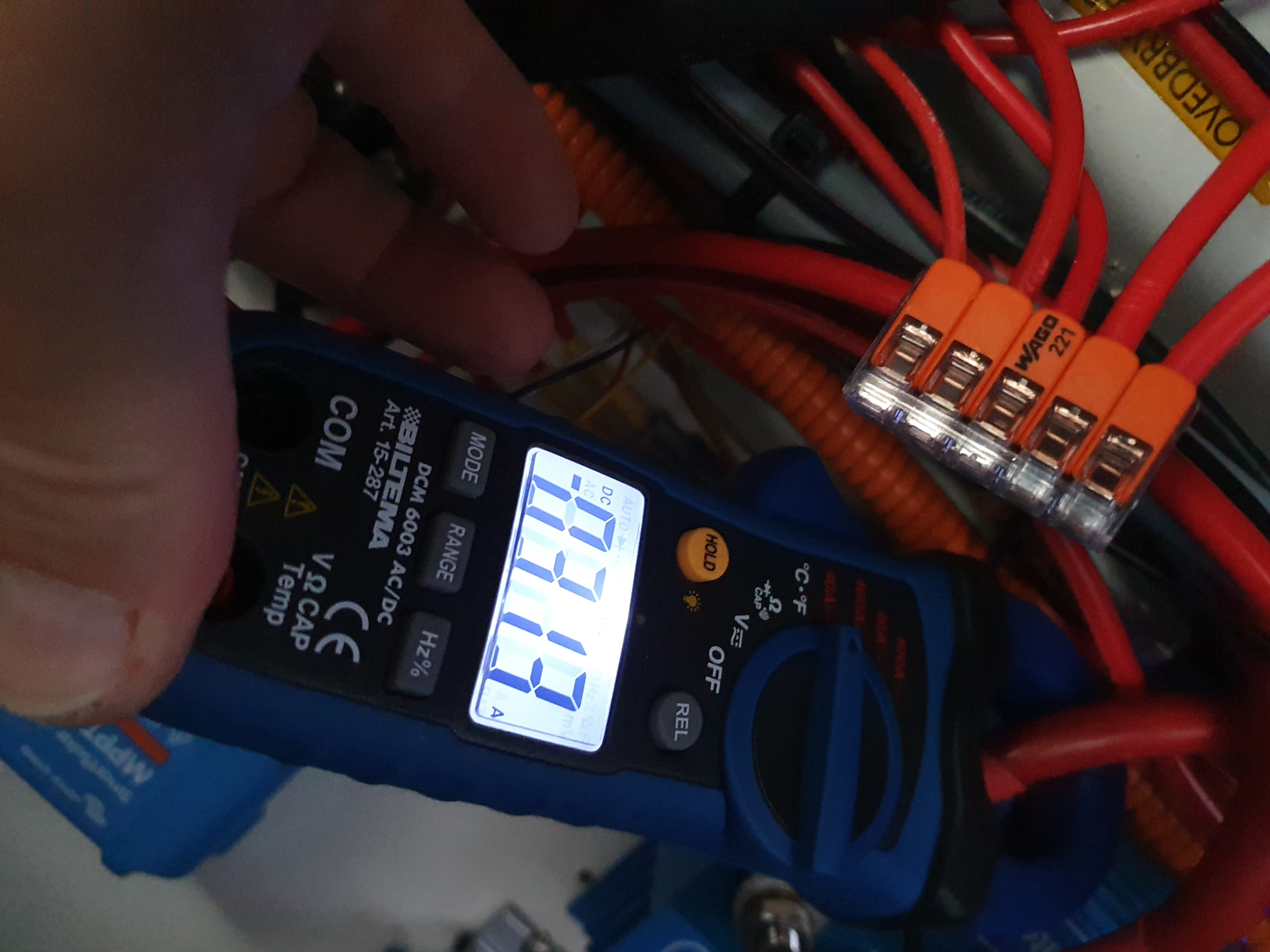
asked
Argo FET 200-2, reverse current flow?
@mmosberg, do you have the "Energize" input connected? If so, disconnect that and see if the current stops. If it does, then you know that you have something wrong in the circuit feeding the "Energize" input. Typically this input would be wired to your start switch so that it doesn't have power unless your start switch is on, but then again you may have wired it to something else, or your start switch is faulty, or any number of possibilities that may be keeping the Input energized.
The fact that you have reverse current running down your Input, however, strongly indicates that you have a short or some consumer on the Input circuit, which warrants its own investigation. An electrical system properly connected and at rest should definitely not be consuming ~3A; even less so when the only thing that should be on the other end of that cable is your alternator or generator. Some thing -if not several things- is/are wired incorrectly in the system, so I'd advise chasing down what is consuming that power first and foremost, then after that's fixed, go back to the ArgoFET and make sure that you have that properly wired as per the manual.
@Justin Cook. Thx for replying.
If i turn the starter main-switch to "Off", then the leakage stops. Also if I disconnect the "Energize" the leakage stops (still measure 0,2 A).
I have 3x100A LifePo4 batteries in the aux bank, and 2x100A AGM start bank batteries. However, the engine ECU is connected to the aux bank, as pr Yanmar recommendations to prevent ECU blackout while turning the starter. I can see that there is a + cable running from the ECU to the alternator which again is connected with the starter. So the leakage I have can be explained by the fact the higher LifePo4 voltage at 13,3V compared to the 12,9V AGM voltage causes a current of app 3A.
Now I assumed that the Argo FET 200-2 provided a 100% tight non return functionality and that the Energize output was about trigging the alternator to start charging. I could at least not find any info about the opposite. If I am wrong, and my Argo FET 200-2 behaves as designed, how can I solve this problem? I want a 100% tight separation of the battery banks. My emergency contingency is maintained with a separate "Emergency X-over" switch between the banks. Thanks for helping.
@mmosberg, it seems like a couple of things could be said:
You have your Energize input wired to something that's always-on instead of to a start switch as shown in the manual. Rewire that so that it's only live when you go to actually start the engine and your problem (theoretically) will be solved.
That being said: 13.3v LFP to a 12.9v AGM does not equal 3A of current. There's definitely something else on the system that's consuming that power, so I must again advise you to track down what that is and resolve that. Once you rewire the Energize input, I guess it's not all that relevant, but bottom line is it's a consumer that you're not aware of, so I suggest that you track it down just so you can identify whether it's a problem or not.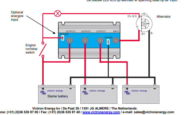
Thx again. I will try to find another energize source. I think it is the ECU together with the leakage that represents the 3 A. As mentioned above the ignition/ECU is powered by the aux batteries. And the starter batteries and the aux batteries are interconnected because of the plus wire running from the ECU to the generator and from there to the starter.
However, my question remains. Isnt the Argo FET 200-2 supposed to be 100% tight, meaning no backflow? In my previous boat I had a old fashioned conventional diode (Volvo make) and there was no backflow there. There is no info about this in the documentation as far as I can see. Anyway I am mostly interested in a sollution. What kind of device can I use to prevent the backflow?