question

markus avatar image
markus asked

Hydro Generator Brake - how?

Hi,

I know this question has nothing to do with Victron equipment in first place, but I think there are good electronics engineers around in this board, maybe someone can help me.

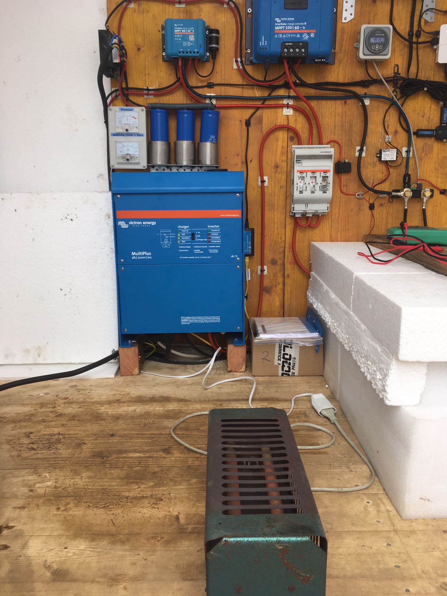
I have had a hydro power installation with a Victron MPPT Charge controller.

See: https://www.victronenergy.com/blog/2017/12/18/diy-ingenuity-hydro-power-in-the-austrian-alps/
Unfortunately, a heavy storm and the affiliated flood flushed it all away.

I'm just about to rebuild everything bigger and better now. You can read about it in a near future blog from John Rushworth, when it is finished.

The problem I am heading now is, that the open circuit voltage of my generator after rectification is above the maximum MPPT input Voltage of my charger.

My charger accepts a maximum of 250V and the Voc of the generator is 300V.

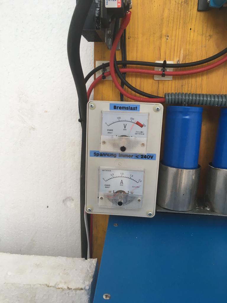
My conclusion is to find a solution to electrically brake the generator so the Voc stay safe below 250V

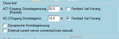
I have to put a 1Ampere load to the generator to brake it down to safely below 240V


I have 3 approaches to solve this, but I do not know which way to go.


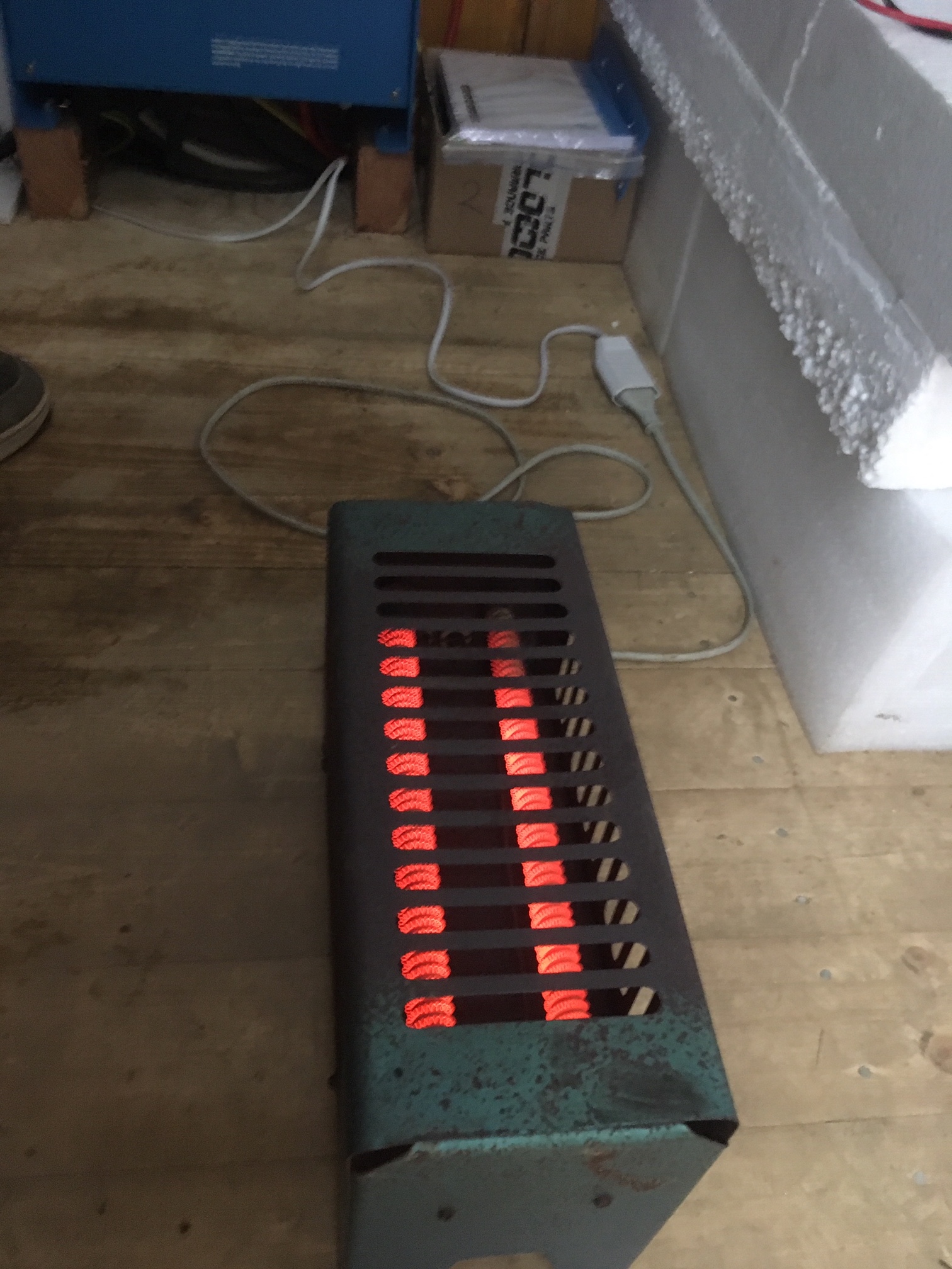
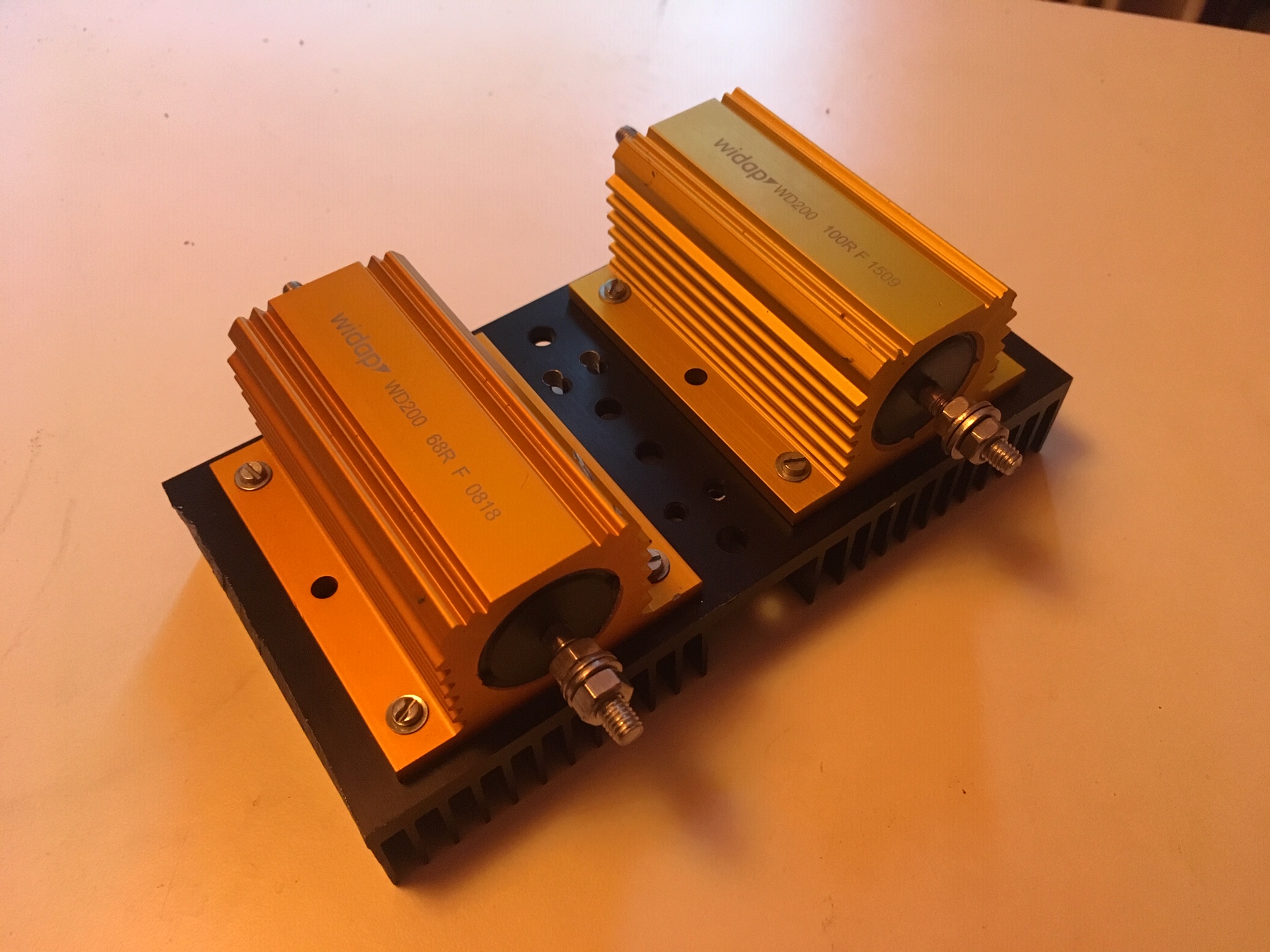
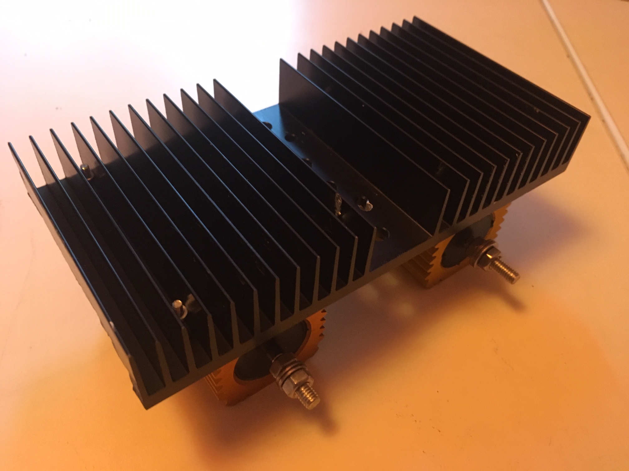
1.) connect a power resistor in parallel to the generator to brake it

This would be the easiest way to solve this, but I will lose usable energy through the resistor.

I do not like this solution


2.) build a voltage stabilisation circuit with a transistor and a Z-diode that short circuits the generator at e.g. 230V and over to brake but does not apply below 230V.

This is the most complicated solution, but a good one I think.

The problem here is, that I would need some help to calculate the components of the circuit.

I am just not good enough to do this completely on my own.


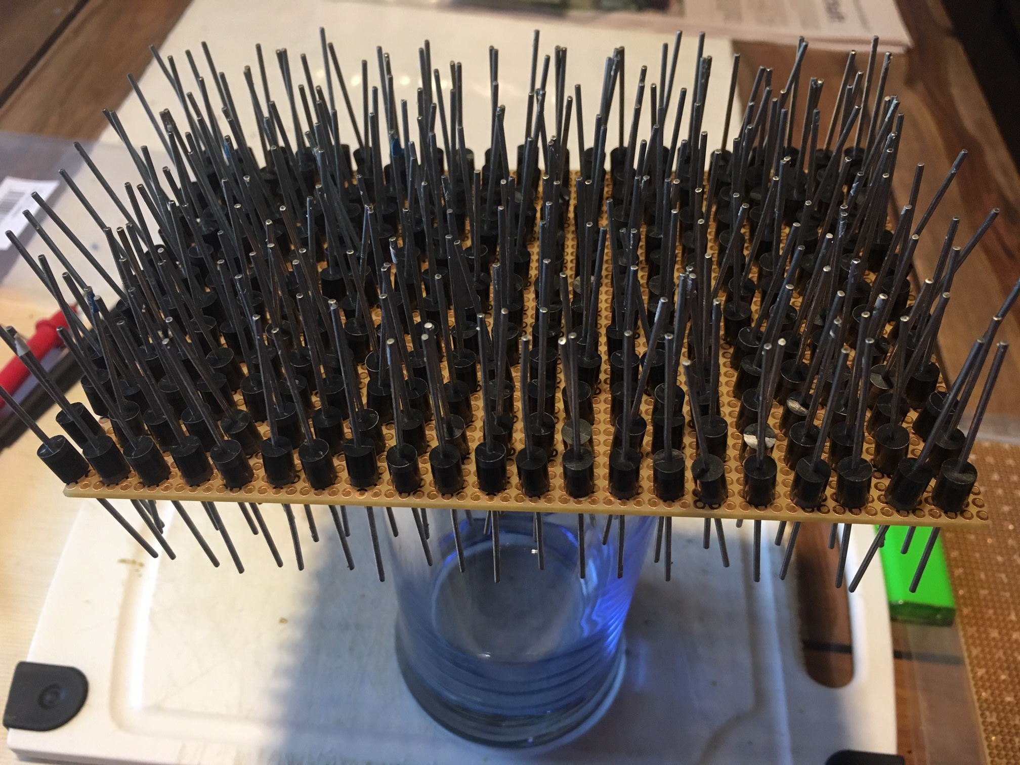
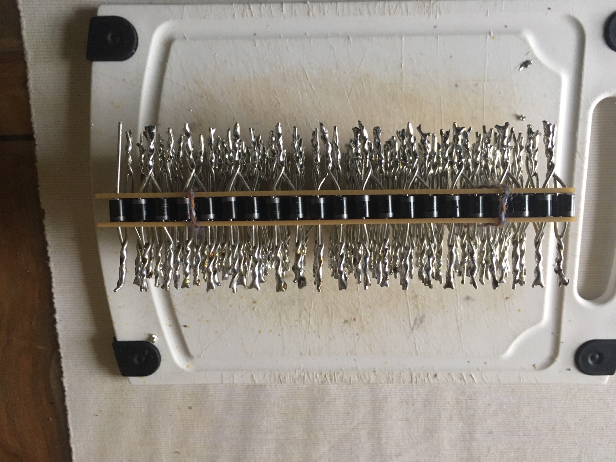
3.) build a serial diode brake.

The approach here is, that a silicon diode is not conductive in transmission direction below 0.7V

You can get 5A silicon rectifier diodes very cheap.

So when I solder 300 of them in serial and connect them in parallel to the rectified generator output, that should to the trick.

The diode characteristics would then be my generator "brake characteristics"

This is a bit of a dump solution but I do like it. The cost of 300 diodes would be around 30€.


The idea behind posting this here is, that maybe someone has a better idea.

I would tend to go and solder some diodes. :o)


Thanks,

Markus

MPPT ControllersHydro and Wind Power
2 |3000

Up to 8 attachments (including images) can be used with a maximum of 190.8 MiB each and 286.6 MiB total.

11 Answers
wkirby avatar image
wkirby answered ·

Solution number 2 is the best, although I'd use a resistor divider and a voltage comparator or opamp which can also offer the ability easily implement and adjustment pot for finer control. The opamp will drive a MOSFET to turn on a big dump resistor.
It would be good to include some hysteresis to prevent the setup from oscillating, the dump resistor remains turned on for a few seconds until the MPPT has taken hold.

5 comments
2 |3000

Up to 8 attachments (including images) can be used with a maximum of 190.8 MiB each and 286.6 MiB total.

markus avatar image markus ♦♦ commented ·

Thank you, I will look into that. I have found some sample circuits online.

I don't like the fact that those circuits tend to oscillate.

Markus

0 Likes 0 ·
wkirby avatar image wkirby ♦♦ markus ♦♦ commented ·

I have done some more thinking. Remember that option 2 is an active circuit, so it will need to be provided with a constant low voltage power supply. A self powered design is possible with a high voltage MOSFET or an IGBT but you'd probably still need to control the oscillations.
The 300 diodes design is of course passive and can live next to the river where it can clamp the voltage close to the source. You still need a power resistor in series with the string of diodes too.

0 Likes 0 ·
markus avatar image markus ♦♦ wkirby ♦♦ commented ·

(1/2)

Hi WKirby,

Thank you so much for helping me here, I appreciate.

My thoughts on the diodes solution are, that a power resistor is not necessarily needed.

I need to apply only a 1 Amp load, to break the generator below 240V, according to the diodes datasheet the voltage drop at 1 Amp is about 0.9V

So 0.9Watts of heat is generated in each diode. This is not so much.

The diodes I would choose have a maximum rated average forward current of 5A

I have a design in mind to stick the diodes in a breadboard to get a handy package and solder the wires at its full length to support cooling of the diodes.


0 Likes 0 ·
markus avatar image markus ♦♦ markus ♦♦ commented ·

(2/2)

I can use a clamp to short circuit some diodes to do fine tuning.

What do you think, am I wrong with my hypothesis?

I think this solution would be a simple method and a stable one.

Thanks,

Markus

0 Likes 0 ·
markus avatar image markus ♦♦ wkirby ♦♦ commented ·

Hi @WKirby,

I did some soldering and just tested the "serial diode brake".

It basically works, but the diodes get too hot at test current of only 0.4A

It felt like, the closer the diodes are to plus, the hotter they get.

This is the Datasheet of the diodes I used: https://hifituning24.de/downloads/by500.pdf

They have a rated continuous forward current of 5A.


Why do they get hot at only 0.4A?

Why do they get hotter, the closer they are to plus?

What where your thoughts in suggesting a power resistor in series?

Thank you so much for help.

Regards,

Markus


0 Likes 0 ·
markus avatar image
markus answered ·

It seems that I have under estimated, what it means to "burn" 250 Watts.

I do not get enough of the heat away from the diode bridge and to throw it into the river to cool is no real option ;o)

I now connected a BIG Power Resistor in parallel and this seems to be my final solution, as the Power loss at full load is below 100Watts.

I will live with that.


You can read about this project in a near future blog from John Rushworth.


Thanks,

Markus

3 comments
2 |3000

Up to 8 attachments (including images) can be used with a maximum of 190.8 MiB each and 286.6 MiB total.

wkirby avatar image wkirby ♦♦ commented ·

Ah, I'm sorry, I kinda lost track of this!
Well, I'm pleased that it's working, but I think having that same resistor in series with the diode array would prevent so much power being dissipated in the diodes and save so much wasted energy. But if it's working out for you as it is then that's great!
Looking forward to the blog update.

0 Likes 0 ·
markus avatar image markus ♦♦ wkirby ♦♦ commented ·

Thank you anyway,

yes i will try a combination, but one thing I don't get with this is, that i will need 1Amp+ of current to brake. As long as i have a serial string, I cannot lower the current through the diodes over a serial resistor... I will deep dive into this matter in future. But for now I am happy :o)

0 Likes 0 ·
img-5586.jpg (743.3 KiB)
img-5587.jpg (665.4 KiB)
img-5545.jpg (1013.7 KiB)
img-5547.jpg (912.9 KiB)
wkirby avatar image wkirby ♦♦ markus ♦♦ commented ·

That is awesome, I don't think I'd have the patience to assemble that diode array, good work!

0 Likes 0 ·
markus avatar image
markus answered ·

After final optimizations and nozzle setup, I do have 341Volt oc :o/

Lessions learned. First do complete nozzle set up, then calculate and buy brake resistors. :o)))

So I have to actually "waste" 900Watts.

I found the perfect device for that:

Solved generator Voc and heating the site in one solution :o)


I now have 1500W of continuous Hydro Power from MPPT or 900W of heating power.

Maybe I consider some downsizing, fo my next Hydro Installation ;o)

I have to replace the Amperemeter, to match the brake load...


Regards,

Markus


3 comments
2 |3000

Up to 8 attachments (including images) can be used with a maximum of 190.8 MiB each and 286.6 MiB total.

mvader (Victron Energy) avatar image mvader (Victron Energy) ♦♦ commented ·

Cool! (Or, hot! :-). )

0 Likes 0 ·
wkirby avatar image wkirby ♦♦ commented ·

Excellent work! Hope the wasted heat is useful. Is it possible to heat water too?

0 Likes 0 ·
markus avatar image markus ♦♦ wkirby ♦♦ commented ·

Hi WKirby, yes this would be the next step. :o) You can't use a normal water heater, as it is controlled over a thermostat. I am searching now for a solution (a temperature controlled valve), wich opens up at e.g. 80°C and let cool water in and closes again at 60°C.

Another solution would be, to build a heated bathing lake... :o) ...this would be such a good thing to have up here in the mountains...

At the moment we get warm water from a gas water heater supplied by bottled gas.

0 Likes 0 ·
samin8r avatar image
samin8r answered ·

Cool stuff. I have a similar install underway by the means of in river hydro and have to convert 220vac to 200+vdc for a similar controller circuit.

My rated output is 2000w at 220vac.

Any ideas on a AC-DC converter?
2 |3000

Up to 8 attachments (including images) can be used with a maximum of 190.8 MiB each and 286.6 MiB total.

markus avatar image
markus answered ·

Hello @samin8r,

thanks. It would be very interesting, to read more of your installation.

Do you have 2 Phase AC or 3 Phase AC generated by your hydro generator?

You have to be very careful, not to exceed Open Circuit Voltage of the charger.


For AC to DC rectification calculations regarding open circuit voltage, I would just use AC*SQRT2 for DC Open Circuit Voltage calculation.


Be aware that rectification of 220V AC, result in over 310V DC, but as you said it is producing 2KW at 220V. The unloaded AC voltage of the generator will likely be much higher.


In this dimensions (2KW and over 310V), I would not prefer to choose a MPPT DC charger based on what I have learned.

I would chose a PV inverter, capable of handling those high Voltages and feed this AC to a Multi. But this is only a suggestion and choosing the right solution depends on many things.


But it is also important to have some braking, in case of an unloaded situation of the wheel. Your bearings will be thankful. And an unloaded waterwheel spinning at very high speeds, sounds like a siren.


But this is a very interesting theme and also funny to build, to have and to maintain. :o)


If you have further questions, I would be glad to help.


You can get a bridge rectifiers really cheap, on common online trading platforms ;o)


And I hope it is clear to everyone that playing around with those high voltages is very dangerous and you should only work with those voltages if you know exactly what you are doing.


PS.: Dont make the same mistake I did and make calculations and buying hardware before you have set up your hydro generator with the right sized nozzles... ;o)


Best Regards,

Markus


2 |3000

Up to 8 attachments (including images) can be used with a maximum of 190.8 MiB each and 286.6 MiB total.

samin8r avatar image
samin8r answered ·
Markus

Thanks for the response. The units are quite well finished machines from China. They are a 48DC which then is put through an Inverter to make 220VAC. I have quite a cable run and need to keep the voltage up for loss's. I did plan to use a bridge rec to swap back to DC but was trying to work out capacitor sizing? But if putting this through an Inverter the need to smooth out the wave form may not be an issue? The turbines have a braked system built into the controller hardware which is great.

I am utilizing a Quattro which has the two AC In terminals which would be ok for an Inverter hook up. Though I'm not sure if AC load is larger than AC2 Input whether it starts to stall the input? I have been running on solar for a year now and am keen to get this going as a supplement during adverse weather.

1 comment
2 |3000

Up to 8 attachments (including images) can be used with a maximum of 190.8 MiB each and 286.6 MiB total.

markus avatar image markus ♦♦ commented ·

Why do you want to swap back to DC? I don't really get, why you need it.

0 Likes 0 ·
samin8r avatar image
samin8r answered ·

You are probably correct? I was thinking about putting it through an MPPT and it could supplement the other MPPT's?

My only concern was whether the Quattro would stall AC load In 2 connection if the load was larger? It shouldn't and with Generator Input 1 it has never before?

I was informed by a person within the industry it may stall the Hydro but I think that may be false?

1 comment
2 |3000

Up to 8 attachments (including images) can be used with a maximum of 190.8 MiB each and 286.6 MiB total.

markus avatar image markus ♦♦ commented ·

Hi, you can limit the AMPs of ACin1 and ACin2 separately in VE.Configure.

Setting an appropriate value should prevent your Hydro Inverter from being overloaded.

0 Likes 0 ·
boekel avatar image
boekel answered ·

Why don't u use a transformer? A 3 phase 400v-230v transformer should work. If you place it close to the battery it also saves a bit on wire losses, and gives you galvanic isolation.

other option is of course to lower the rpm (bigger wheel?) but that would mean a lot of work I guess.

5 comments
2 |3000

Up to 8 attachments (including images) can be used with a maximum of 190.8 MiB each and 286.6 MiB total.

markus avatar image markus ♦♦ commented ·

Hi @Boekel,

that sounds like an interesting suggestion, but I don't exactly get what you mean.

Can you further describe this idea?


Thanks and kind regards,

Markus

0 Likes 0 ·
boekel avatar image boekel ♦ markus ♦♦ commented ·

Just a regular transformer to step down the voltage...

Only I don't know what the effects are of higher frequency on a transformer made for 50/60 Hz

0 Likes 0 ·
markus avatar image markus ♦♦ boekel ♦ commented ·

Nice Idea, but in his case there is an inverter producing (stable) 220VAC from the turbines DC. In my opinion, feeding it directly to AC in of the Quattro without converting it, may be a good solution. Converting it back to DC will not bring advantages regarding cable losses... No need of a 2nd MPPT, no need of conversion...

1 Like 1 ·
markus avatar image markus ♦♦ boekel ♦ commented ·

@Boekel Transforming the voltage down with a transformer was another thing i thought, lets say as solution 4, regarding my original "braking" problem.

The problem is, a very high speed of the wheel when unloaded. It is very noisy and the bearings go bad very fast.

So a keeping the voltage down, in braking the wheel has advantages.

Most small hydro turbines produce neutral less 3 phase AC, so you need 3 transformers minimum?

listen to 2500 RPM, imagine when it goes up to 4500 completely unloaded:


Your browser does not support HTML5 video.

0 Likes 0 ·
hydrovideo.mp4 (14.7 MiB)
boekel avatar image boekel ♦ markus ♦♦ commented ·

If you solve the high voltage problem, you can use an AC loadshed in your house, like a water heater of another power hungry device.


at least you don't have to worry about overvoltage. you might also consider a valve to close or partly close the water supply when you don't need all the power.

0 Likes 0 ·
samin8r avatar image
samin8r answered ·

This device is already set up with a governor from the factory. It is a run of river generator and thus the rpm is quite low and more linear.

It is 48vdc from the generator and the factory controller steps it up to 220vac. '

Thanks for the ideas though.

1 comment
2 |3000

Up to 8 attachments (including images) can be used with a maximum of 190.8 MiB each and 286.6 MiB total.

markus avatar image markus ♦♦ commented ·

It would be very interesting, if you could share a link from your hydro systems manufacturer.

The non linearity of the wheel is because our house water pump was running on and stopping several times, while I made that video.

Thanks,

Markus

0 Likes 0 ·
enda-mcl avatar image
enda-mcl answered ·

Markus. I have discovered your hydro story and found it excellent. I have similar plans, although with less head and more flow. I’m also looking to use an existing under utilised 250/100 Victron MPPT (secondary solar array, in winter shade). Firstly, I’m interested in your hydro units. They look very robust and well made. Could you provide a supplier? Regards

Enda


1 comment
2 |3000

Up to 8 attachments (including images) can be used with a maximum of 190.8 MiB each and 286.6 MiB total.

markus avatar image markus ♦♦ commented ·

Hi, Thank you!

I bought them off Ebay from a German supplier. They are still available.

See here: Kleinstwasserkraftwerk 500 Watt - Pelton Wasserturbine Wasserrad Generator KWK | eBay

BR

0 Likes 0 ·
vladimir-1 avatar image
vladimir-1 answered ·

Ahoj Markusi, nemůžu tě zastihnout. Dělám něco špatně?

2 |3000

Up to 8 attachments (including images) can be used with a maximum of 190.8 MiB each and 286.6 MiB total.

Related Resources

MPPT Product Page

MPPT Error codes

MPPT 150/60 up to 250/70 Manual

Additional resources still need to be added for this topic