question

waibel avatar image
waibel asked

Alternator not charging with ARGOFET

Hi,

I adopted my engine with an Argofet 200-2, so that I can charge 2 different battery packs. Unfortunately I can't install the Argofet as proposed in the specification, as the ignition switch and the resistor is integrated in my engine control unit.


As proposed in the Victron datasheet:

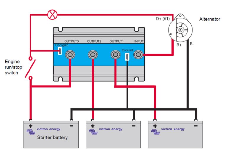
My System looks like this:

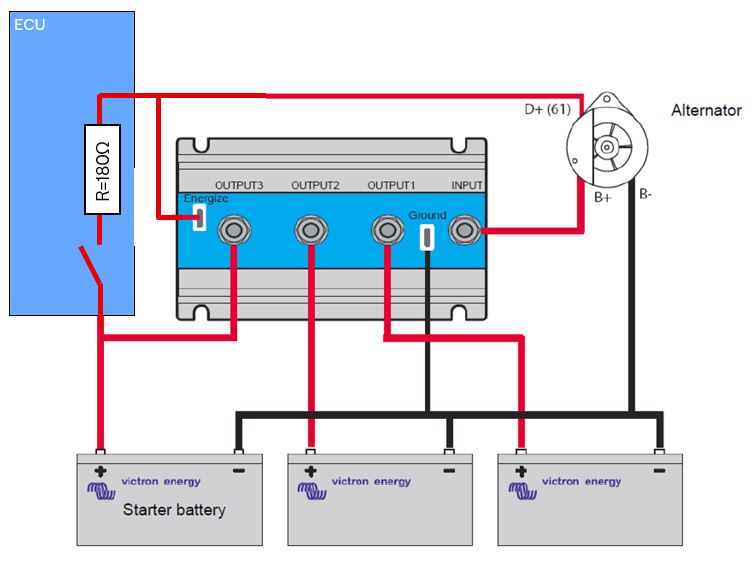
I know that my alternator needs dc voltage at B+, therefore I used the energize Input. Unfortunately this energize input doesn't work in my system and the alternator is not charging and producing voltage. Why has the resistor / lamp to be between Engergize Input and D+?

While testing I accidentaly interrupted the ground cabling from the Argofet. Funnily without ground, everything works fine, but I doubt that's the ideal solution.

Does anyone know how the ArgoFET looks like / works in detail and what could be the reason for the malfunction.


Thanks a lot

Niklas

Argo FET Diode
argofet.jpg (43.1 KiB)
argofet2.jpg (47.5 KiB)
3 comments
2 |3000

Up to 8 attachments (including images) can be used with a maximum of 190.8 MiB each and 286.6 MiB total.

jwfrary avatar image jwfrary commented ·

@Waibel

So your energise input is i suppose you could say a ground of types. You need to connect a live from the battery usually the largest bank, the energise on the argo and the D+ terminal and it will work.

However you need the live to switch on and off with the engine ignition. otherwise the exciter windings in the alt will burn out.

It would be helpful to know what brand/model of engine your working with and we can identify a place to get it from but a lot of manufactures include an ENABLE signal on the harness and you can take it from there through a relay to switch the supply on and off with the engine.

Hope that helps,

0 Likes 0 ·
jwfrary avatar image jwfrary jwfrary commented ·

To clarify, the energize input on the ARGOFET is not provided to energize the D+ of the alternator but to provide a voltage for the B+ alternator input on the Argofet so that the alternator 'sees' a voltage and starts charging. This is the case for some single wire alternators but not a requirement for all. Sometimes you also have battery sense wiring on the alternator and these also need a connection to the battery for the alternator to start charging through an ARGOFET.

0 Likes 0 ·
andreholgersson avatar image andreholgersson jwfrary commented ·
Interesting! Could you elaborate on that? I have a Mando 65A alternator that is fed excitation voltage when the start key is turned to the ignition position. There is also a voltage sense connection on the alternator. Should the latter be connected to the start or service bank? In my case, it would seem that it could be wise to connect the sense wire to the service battery to make sure that the alternator continues to charge, even if the start battery is full?
0 Likes 0 ·
1 Answer
Paul B avatar image
Paul B answered ·

Interesting! Could you elaborate on that? I have a Mando 65A alternator that is fed excitation voltage when the start key is turned to the ignition position. There is also a voltage sense connection on the alternator. Should the latter be connected to the start or service bank? In my case, it would seem that it could be wise to connect the sense wire to the service battery to make sure that the alternator continues to charge, even if the start battery is full?

************************

Note normal alternators D+ this power is fed from inside the alternator from 3 small field control diodes and is used to run the internal rotors power supply via a internal regulator (Usually) the d+ uses a small external excitation current through a warning light to start the alternator and thats all its used for. ( once its excited then the warning light goes out as there is then 12v+ on each side of the warning light thus no current flows across the filiment.

Now you comment that before the d+ was connected directly to your igntion switch now if thats the case the the 3 small diodes in the alternator would have been fried - as they would have suppled power larger than there rating to the hole system (at some point) now once these were fried then the alternator would have ALWAYS taken all its excitation and running power required from the key circuits + connection.

This is my guess from your description if this is the case then take the 1800 ohm resistor out and this should fix your issue as power will then be directly supplied to the d+ then when ever the key is on - (as it was before)

1 comment
2 |3000

Up to 8 attachments (including images) can be used with a maximum of 190.8 MiB each and 286.6 MiB total.

andreholgersson avatar image andreholgersson commented ·

Thank you for your anwser, but I think you misunderstood my question. Nevermind, I'll make a separate post for this.

0 Likes 0 ·