question

gyrex avatar image
gyrex asked

MultiPlus II AC bypass switch help

I've just read the Wiring Unlimited guide - what an amazing and educational resource! Thank you so much to Victron and Margreet Leeftink for writing this, I've really learnt so much about some basic electrical theory.

There's an interesting section in the guide where it suggests running a bypass switch.


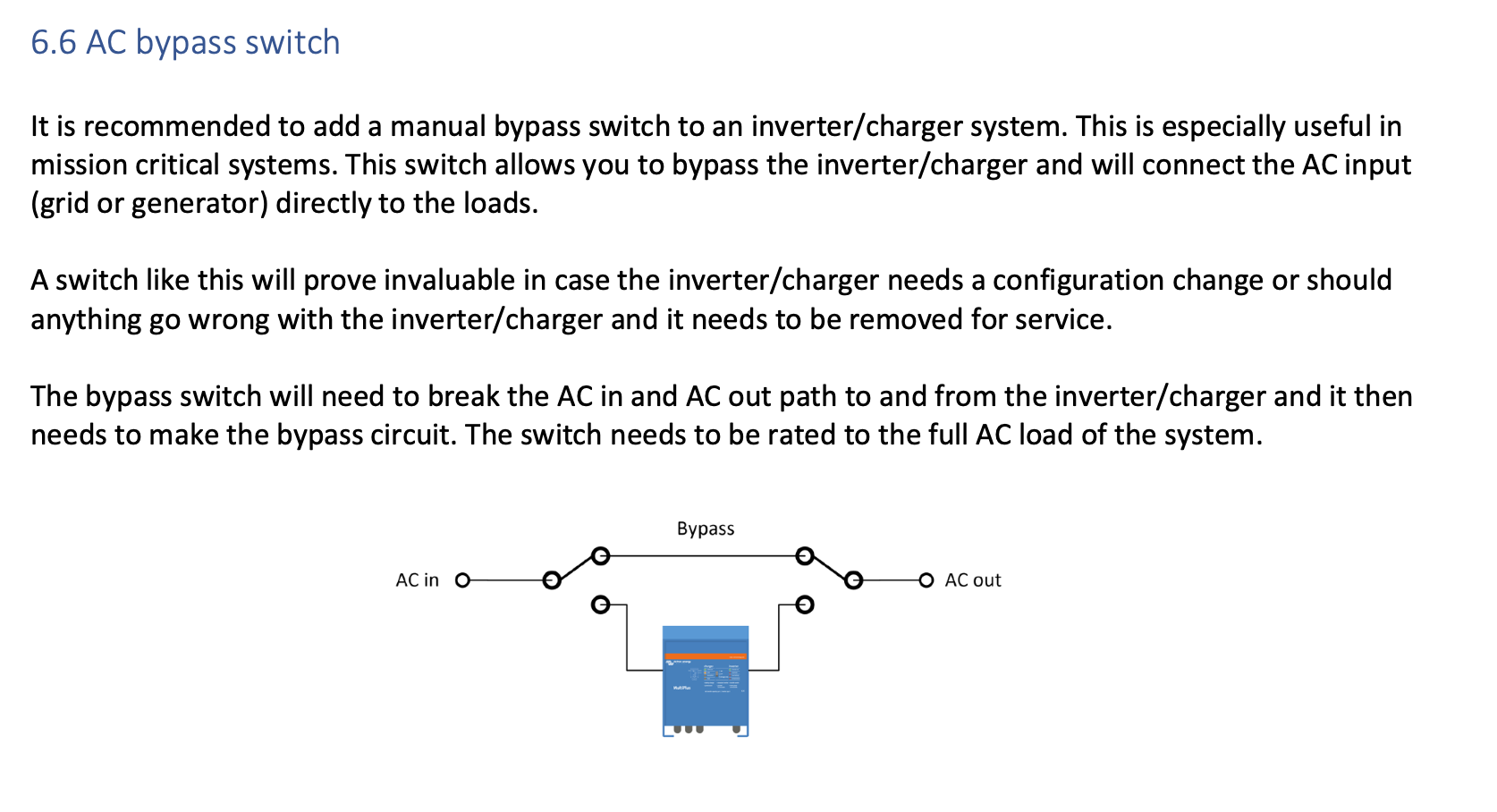
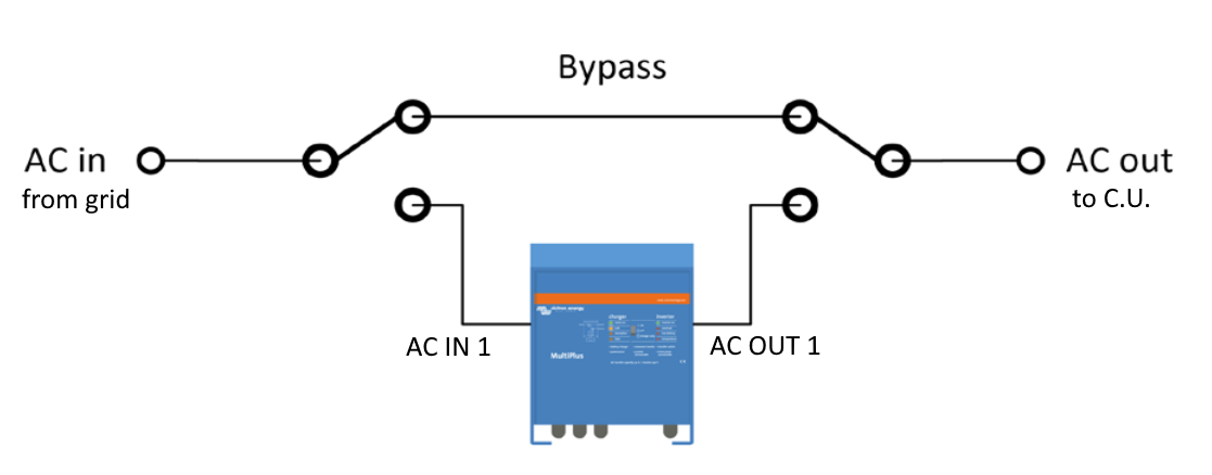
This makes complete sense in order to isolate the inverter from the grid and loads in order to be able to do maintenance etc. but I have a couple of questions:

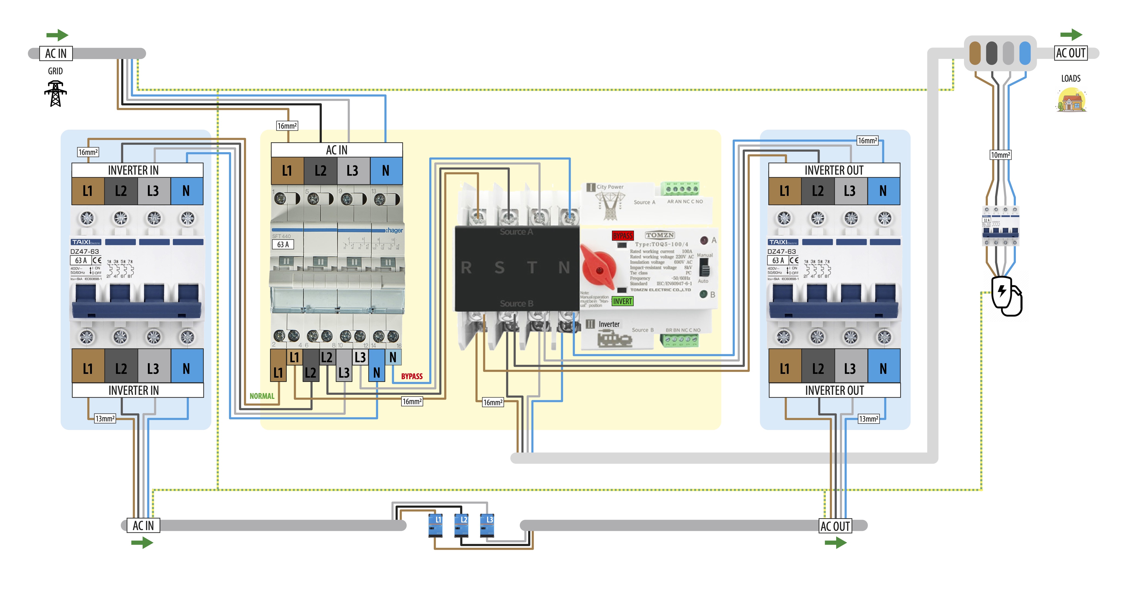
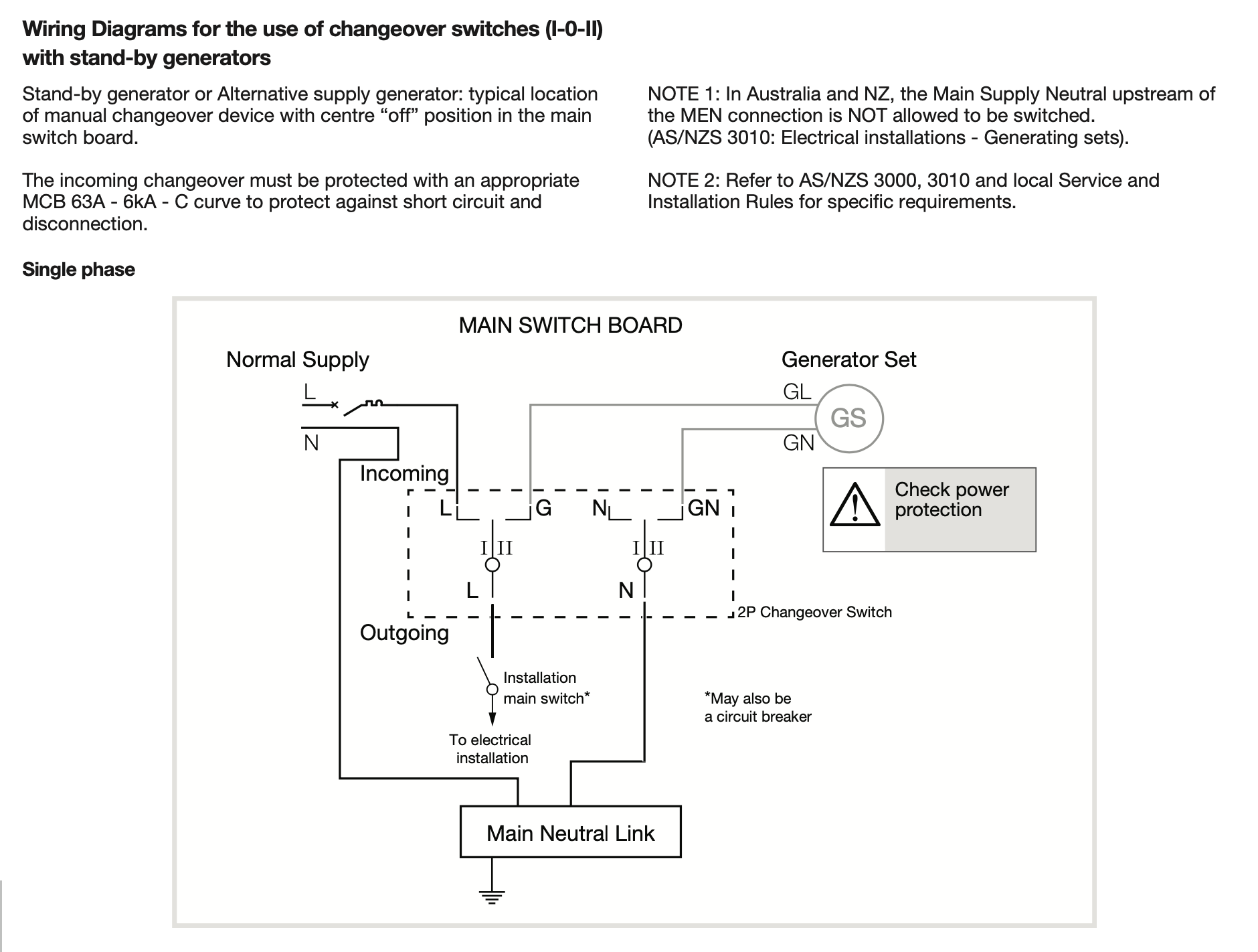
  1. Is a "bypass switch" the same thing as a "changeover switch" such as the Hager SF463? https://www.hagerelectro.com.au/e-catalogue/energy-distribution/control-indication/manual-changeover-switches/changeover-switches/sf463/18978.htm
  2. If it's the same as a changeover switch, how would the switch be wired logically? I've tried working this out but it's not making sense to me and I'm hoping someone might be able to help me understand how this should work?

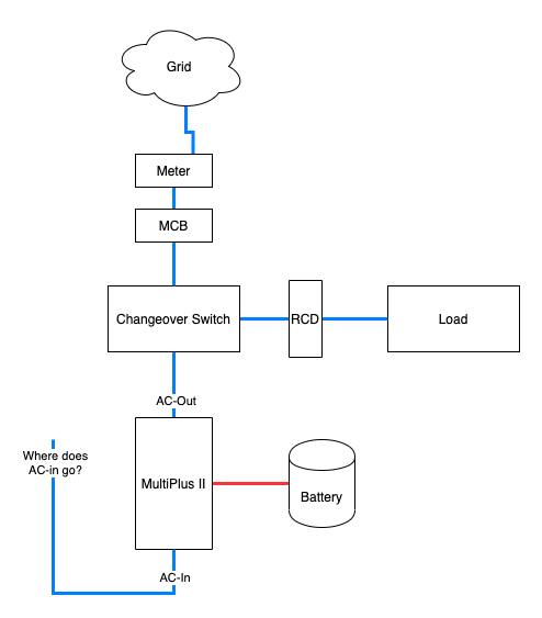
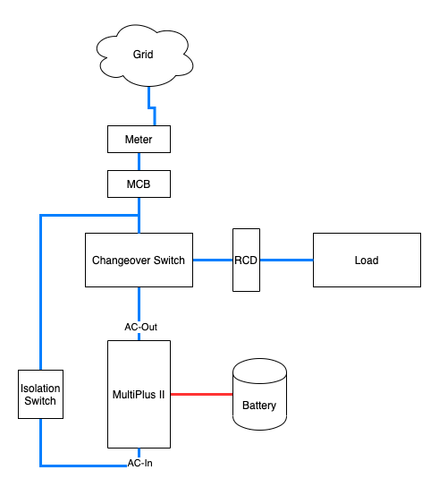
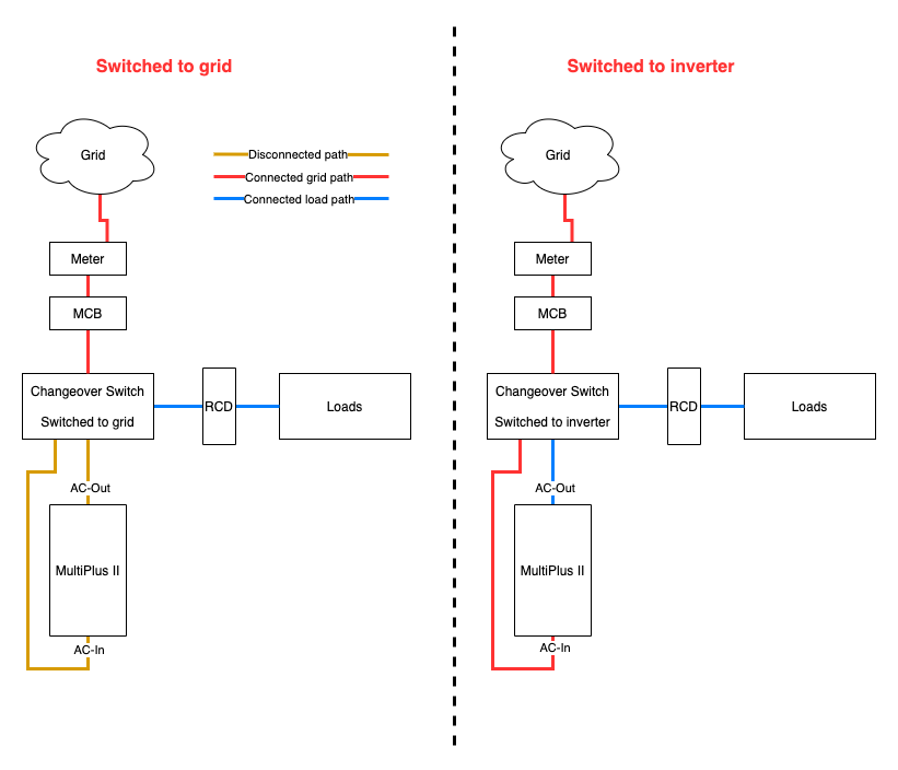
I've got a diagram below which is how I think it should be wired but I'm trying to understand where the AC-In would be wired to.

I thought maybe that AC-In would be wired into the changeover switch in parallel with the AC-out but I thought this might introduce a loop and this would be a bad idea?

Then I thought maybe it should be wired into the output of the MCB but then I'd have to add an isolator and this didn't make sense and doesn't follow the schematic depicted in the wiring unlimited guide.

Would really appreciate some help here from some experts :)

Multiplus-IIwiring diagram
2 |3000

Up to 8 attachments (including images) can be used with a maximum of 190.8 MiB each and 286.6 MiB total.

7 Answers
daryl avatar image
daryl answered ·

back to between the MCB & changeover switch

18 comments
2 |3000

Up to 8 attachments (including images) can be used with a maximum of 190.8 MiB each and 286.6 MiB total.

gyrex avatar image gyrex commented ·

Thanks again for your help Daryl! Like this?

If I do this, even if I switch the changeover switch to mains power, I'm still supplying power to the AC-In of the MP2 which doesn't conform to the diagram set out in the Wiring Unlimited Guide which, when switched, bridges AC-In and AC-Out.

Also, isn't there some danger in that if someone does flick the changeover switch to grid that they'd assume that there's no power being supplied to the 'generator' (that it's isolated) and that it's potentially safe to work on?

Are you able to help me please @Rob Duthie?

0 Likes 0 ·
Rob Duthie avatar image Rob Duthie gyrex commented ·

Hi

Yes you need to install proper AC transfer change over switch which has break before make contacts and lockout.

Which totally isolates the inverter from the grid, as in above diagram 6.6 AC bypass switch.

Regards

Rob D

NZ

0 Likes 0 ·
daryl avatar image daryl Rob Duthie commented ·

Does he? My installer is installing a Hager SF463 generator changeover switch to change the feed for the protected circuits from the output of the Victrons back to the grid.

What is the reason behind needing to also isolate the inputs into the victron at the same time?

0 Likes 0 ·
Rob Duthie avatar image Rob Duthie daryl commented ·

So to have complete isolation when disconnected for service etc.

0 Likes 0 ·
daryl avatar image daryl Rob Duthie commented ·

Sure, you need to be able to remove power from the victrons for service, but that doesn't have to be part of the same switch that moves the protected circuits from inverter-out to grid.

0 Likes 0 ·
Rob Duthie avatar image Rob Duthie daryl commented ·

Hi

For electrical wiring you should be using a electrician to do this for you if you are not qualified to do so. As they should understand what the requirements are for wiring in and isolating inverters to the grid etc.

As this type of work is classified a high risk electrical work in the electrical regulations. and has to be inspected etc.

Regards

Rob D

NZ


0 Likes 0 ·
daryl avatar image daryl Rob Duthie commented ·

I understand and agree. The qualified company designing & installing my system provided a different design to the advice you gave gyrex in this thread, so I am trying to understand the difference. Whilst I may not be a qualified electrician I do have significant data centre operation and electrical design exposure so I am taking an interest in understanding the design of my system.

Effectively I am trying to confirm if your "you need" statement above is more a "I would" rather than a "you must" as I interpret it.


0 Likes 0 ·
Rob Duthie avatar image Rob Duthie daryl commented ·

Hi

You know that the Mulitplus has a change over bypass relay inside it for critical loads AC2 output AC 1 for non critical loads.

You need to advise what model you are using etc.

Regards
Rob D

NZ

0 Likes 0 ·
gyrex avatar image gyrex daryl commented ·

Hi Daryl,

With your design, where has your designer/installer installed the SF463's in relation to the MCB and RCD's (upstream or downstream of these)? I noticed on Hager's website that there's some information relating to having the changeover switch upstream of MEN connections - how does this relate to the location of RCD's?

If you were to wire the AC-in directly to the MCB (per my diagram further up) and bypass the the changeover switch, would this compromise the safety of this circuit because there's no earth path to MEN?

@Rob Duthie

0 Likes 0 ·
gyrex avatar image gyrex Rob Duthie commented ·

Hi Rob,

Thanks for your response. Are you saying that the Hager SF463 isn't a suitable switch for this design?

Is there a transfer/change-over switch which can achieve the following:

When switched to generator/inverter

  • load disconnects from grid
  • load connects to the AC-out on the inverter
  • grid is passed through the switch to AC-in of the inverter

When switched to grid

  • load disconnects from AC-out on the inverter
  • load connects to grid
  • inverter AC-in/out is completely isolated

I'm struggling to figure out how to achieve these goals through a single switch and really appreciate someone knowledgeable such as yourself helping me understand this. I would have thought this would be an easy task but I can't figure out logically how something like this would work.

I'm not an electrician and I will be getting a sparky to install the AC part of the install but I'd really love to learn as much as possible so that I can plan this design and gain some idea of how the design should work.

0 Likes 0 ·
Rob Duthie avatar image Rob Duthie gyrex commented ·

Hi

You need to supply me what the main objective is, and all the equipment being proposed so i have a general idea what is required to wire it up to suit your situation.

Regards

Rob D

NZ


0 Likes 0 ·
gyrex avatar image gyrex Rob Duthie commented ·

My objective is to achieve the following switching illustrated in the diagram below.

0 Likes 0 ·
daryl avatar image daryl gyrex commented ·

The more you post gyrex, the more I suspect we are buying the same system from the same installer.

0 Likes 0 ·
gyrex avatar image gyrex daryl commented ·

I haven't bought mine yet mate - I'm just planning the design and putting together an inventory :) I don't know if you're aware but there's a post I made further up where I asked you questions about where your designer/installer planned to install the SF463. Where do you live mate?

0 Likes 0 ·
Rob Duthie avatar image Rob Duthie gyrex commented ·

Hi

You know that the Multiplus has a built in transfer relay on AC2 output

that can handle 32 amps of load current for the 3kw unit and 50Amps for the 5kw unit.

So why the change over switch? all you need is bypass switch for the inverter.

https://www.victronenergy.com/live/ess:design-installation-manual

0 Likes 0 ·
daryl avatar image daryl Rob Duthie commented ·

My motivation for the changeover switch is to flip the house loads (that normally live behind AC-Out 1) back to the mains if the Victron/Battery system has a failure that it can't self bypass. In a 3-phase configuration I believe a fault in one inverter could cause all 3 to shut down until a repair is completed.

@gryex Essentially my inverters & mains-in on the changeover switch will feed from a switchboard behind the MCB. The AC-out1 on the Victrons will also connect into the change over switch (in the generator port) and the majority of my loads including Solaredge inverters into the load side of the changeover switch.

0 Likes 0 ·
gyrex avatar image gyrex Rob Duthie commented ·

I think you're mistaking AC-Out-2 and AC-Out-1 Rob. There's no UPS function (no inverter power) supplied to devices connected to AC-Out-2 in the event of grid failure.

I'd like to implement a changeover switch as part of the design in case I need to do work on the inverters or if one of them fails. It means I can easily flick a switch and move my loads to the grid.

From the MP2 manual:

0 Likes 0 ·
Rob Duthie avatar image Rob Duthie gyrex commented ·

Hi

Yes there is, as this is how my system works as i have Mulitplus 2 wired this way as a UPS backup and grid feed back etc.

I had no power bills for about 5 months now and in credit with power company.

After i reconfigured my system to use lithium batteries and inserted the current CT into main incomer.

Have as lool at the below document

Victron MultiPlus-II-to-MultiGrid-and-MultiPlus-comparison-EN wiring.pdf

0 Likes 0 ·
raphael303 avatar image
raphael303 answered ·

I believe nobody really has answered your original question 1.

No, a changeover switch is NOT the same as a bypass switch as displayed in the drawing by victron.
A changeover switch is ONLY ONE HALF of a bypass switch. With it you could switch the Grid from the input of the multi over to the input of the house.

BUT since the output of the multi is connected to the house you would then have Grid-AC on the output of the multi, but not on the input.

So you need ANOTHER switch, which disconnects the output from the multi from the house and changes it over to the output of the first switch, which then is grid power.

You COULD do it with TWO changeover switches. But the would be a very bad idea, because wrong use of the switches could lead to exactly what I described above.

So you really need a bypass switch, which is two switches in one. I don't know of one. Sorry.

As an alternative you could just use one changeover switch on the output of the multi. To changeover the house from the multi to the grid directly. This would leave the multi connected to the grid, but without anything on the output. That would not hurt and accomplish having the house uninterrupted on the grid.

2 |3000

Up to 8 attachments (including images) can be used with a maximum of 190.8 MiB each and 286.6 MiB total.

nikbok avatar image
nikbok answered ·

What do You think about this idea?

One click bypass switch (semi-automatic). Combination of manual change-over switch (MCS) and automatic transfer switch (ATS). When MCS is manually switched to bypass, ATS will automatically recognise grid input wich is prioritised and disconnect secondary source (inverters) from the house (loads) and connect bypass(grid). When switched back to "normal/inverter" position "grid" on ATS will go down and ATS will switch over to secondary source (inverters). With decent ATS, automatic switching can be done in 2-5ms.

bypass-v2.jpg


bypass-v2.jpg (956.6 KiB)
2 |3000

Up to 8 attachments (including images) can be used with a maximum of 190.8 MiB each and 286.6 MiB total.

raphael303 avatar image
raphael303 answered ·

This idea is only a bypass if you manually break the circuit-breaker on the left. Before you break that one the multiplus will still have grid input.

I don't know if that is a problem in the long term, but really don't think so.

Nevertheless, this allows you to bypass. just not with one turn of a switch.


As for the ATS. The one in the image I'd certainly not use... Looks a little bit too... uhm.. foreign-certified to me.

And, why use an ATS anyways? It doesn't need to be automatic for your idea. It can be manual. You win nothing by it being automatic, since you manually break breaker on the right anyways.


So you could just forget the right circuit breaker and use a manual changeover switch instead of the ATS. Then, once you turn the manual changeover, break the circuit on the right and you have your bypass.


2 comments
2 |3000

Up to 8 attachments (including images) can be used with a maximum of 190.8 MiB each and 286.6 MiB total.

nikbok avatar image nikbok commented ·

First, when you tripp change-over switch (hager) to position 2 (bypass) it will disconnect CB on the left from the grid and ATS will automatically disconnect CB on the right from the AC loads. Doing so multis will be disconnected from grid as well as from AC loads, which is pupose of bypass switch.

Multies will still be powered by DC and fully functional BUT disconnected from AC and what is more important AC loads will be powerd from grid, enabling you to service multies.

Second, CBs on the left and right (in light blue) does not have anything to do with bypass switch, they are there purely for safety. You do not need to touch them at all.

Third, yes - you could do the same with two manual change-over switches (COS), I just find this combo easier to use and less to think about. Position I - inverters , Position II - bypass.

With two manual COS you would need to switch left COS first and then switch right COS to go to bypass and other way arround (first right and then left) when going back to normal inverter mode. Possible but not as nice as mine semi-auto ;)

As for the this ATS, well yes, it is from china as our phones, computers and all other stuff made in china but branded with western brands and sold for 10x the price.

Do you have suggestion on solid reliable ATS?

1 Like 1 ·
raphael303 avatar image raphael303 nikbok commented ·
I see. I didn't get the Hager was a changeover. Thought it was just a breaker.

Alright. Seems smart to me! :)

As for the ATS from China. The point is not that is made IN China.
The point is if it is made FOR China.

A European product made in China according to European standards, quality testet to European standards is totally fine. See phones, computers.

A Chinese Product made to European standards is totally fine, see DJI.

A Chinese Product made to Chinese standards... well... not so much. See AliExpress, sort of.

0 Likes 0 ·
Rob Duthie avatar image
Rob Duthie answered ·

Using a solid state ATS would not be compliant due to that it needs to be mechanically isolated.

The ones i use which are compliant are from Smart gen in China

They are solid built and the controller can be auto and manual control.

It has built in genstart contact etc.

This is what i use in my transfer and control off grid and on grid applications.

with Victron inverters.

Also note this do not use power like the contactor type ones do with hum etc.

https://www.smartgen.cn/product/100

https://www.smartgen.cn/product/192

Regards

Rob D

NZ

2 |3000

Up to 8 attachments (including images) can be used with a maximum of 190.8 MiB each and 286.6 MiB total.

ronski avatar image
ronski answered ·

My system is installed, and up and running, I've used the method as shown in the wiring unlimited handbook, and as posted in the very first post in this thread. I'm using a Quattro 48/10000.

The AC side of the install was done by electricians, and they used two rather expensive change over switches.

inverter-bypass-circuit.png

My full system schematic can be viewed at this link as well, as even though its only 533KB the system will not let me attach it. Actually it didn't like the filename!


schematic.jpg


Odd, it lets me attach this


switch-gear-wiring.jpg


1 comment
2 |3000

Up to 8 attachments (including images) can be used with a maximum of 190.8 MiB each and 286.6 MiB total.

ronski avatar image ronski commented ·

Forgot this picture.


switchgear.jpg

0 Likes 0 ·
switchgear.jpg (137.4 KiB)
sharpener avatar image
sharpener answered ·

Or an isolator on the input to the inverter and just a single one of these DiN-rail mounting switches to select whether the loads are connected to the AC-Out or the incoming grid.

2 comments
2 |3000

Up to 8 attachments (including images) can be used with a maximum of 190.8 MiB each and 286.6 MiB total.

Craig Chamberlain avatar image Craig Chamberlain commented ·
This is the setup I've got on mine. I think it's better actually because it gives you the flexibility to power up the inverter for battery charging or firmware updates etc but still have your AC-Out 1 loads connected to the grid to avoid interruption until the inverter is ready to take over again.
0 Likes 0 ·
sharpener avatar image sharpener Craig Chamberlain commented ·

Yes, the isolator is mandatory anyway so the single switch is all you need add. And unlike some of the configurations described upthread it is foolproof and does not rely on cable ties(!) or sequencing instructions.

Alternatively in the same space you could get get this changeover contactor plus a 6A mcb to protect the coil circuit and serve as a manual control. Then if the inverter develops a fault while you are away it automatically fails over to the grid.

A previous poster suggested this is not compliant with the grid code as (unlike the inverter's grid isolation cct) there is only one set of isolating contacts, but IMO the likelihood of them becoming welded in a way that will connect AC-Out to the grid is pretty small.

0 Likes 0 ·

Related Resources

MultiPlus-II Product page 

MultiPlus-II Manual

MultiPlus-II 230V Datasheet 

VE.Bus Error codes

Additional resources still need to be added for this topic