question

stdl avatar image
stdl asked

MPII 3pH System Generating 'Ghost' Overloads/Earth Leakage Trips/Unequal Feedback through Grid Meter

Hi All,

We have 6 x 3kVa MPIIs working in parallel on a 3pH system. We have a 20amp 3pole breaker on the critical loads side protecting the system from overloads. Yet we continually get Overload warnings and when the Mains Grid drops out we often get full overloads.

The VRM load traces are set to 1 min and show no signs of these overloads.

The units are in an AC controlled room at 19deg.

The critical loads circuits had Earth Leakages that did not trip pre system install, yet tripped everytime the mains Grid dropped out. Client removed the ELs.

Lastly we have mppts charging the li ion battery and yet even with Phase Comp on ESS we have uneven power delivery, to the extent that 'spare' power is pushed back through the Mains Site meter though one or two of the phases, constantly.

System was installed by engineers with Victron training. System VRM has been reviewed by high level Engineers with Victron training. No solutions to date.

SLD For Victron.pdfSLD attached.
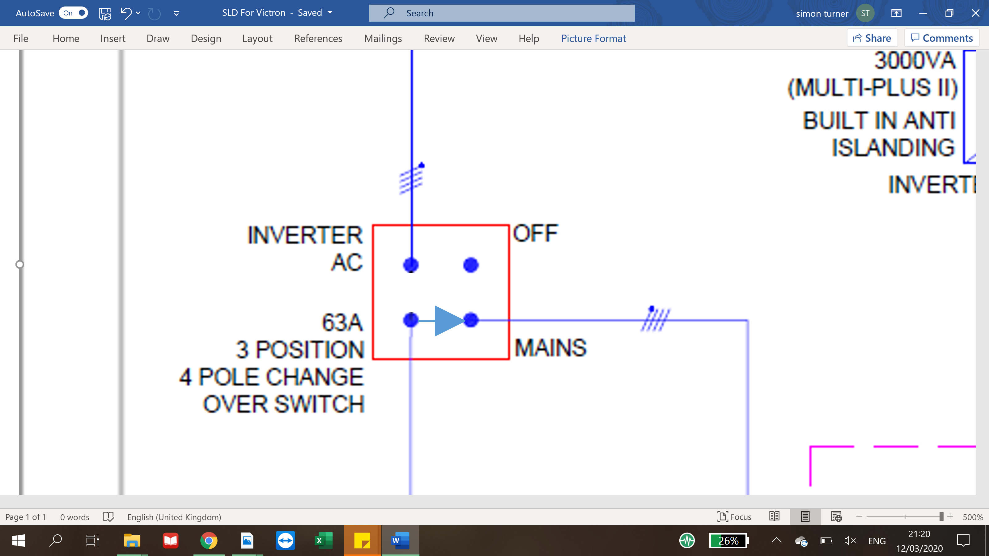
Multiplus-IIMPPT Controllers
sld-for-victron.pdf (110.0 KiB)
1 comment
2 |3000

Up to 8 attachments (including images) can be used with a maximum of 190.8 MiB each and 286.6 MiB total.

Warwick Bruce Chapman avatar image Warwick Bruce Chapman commented ·

Please share the exact errors. Are you sure they’re not error #11?

0 Likes 0 ·
3 Answers
Daniël Boekel (Victron Energy Staff) avatar image
Daniël Boekel (Victron Energy Staff) answered ·

Hi @STDL

First thing I noticed: the 'Changeover switch' is not ok: when you set the output to 'mains' instead of to 'inverters' you will put mains input on the -output- of the inverters, this -will- damage them, please have that changed.


2 |3000

Up to 8 attachments (including images) can be used with a maximum of 190.8 MiB each and 286.6 MiB total.

stdl avatar image
stdl answered ·

Hi Daniel,

No the AC1 Output is totally disconnected by the bypass switch. The SLD is just showing the switch position which allows power to feed to Crit loads from the AC1 Out. There is no back feed of mains into AC1 Out.

3 comments
2 |3000

Up to 8 attachments (including images) can be used with a maximum of 190.8 MiB each and 286.6 MiB total.

That's not what the drawing says, so than the drawing is not correct.

0 Likes 0 ·
stdl avatar image stdl Daniël Boekel (Victron Energy Staff) ♦♦ commented ·

On the SLD, the switch arrow, inside the 'box' indicating the bypass switch, could be indicated in one of 3 positions. In our example (SLD) it is pointing at the AC output 1 Line(s). If we were to change that, to indicate another option of the 3 senarios, the switch arrow could be pointing at 'Mains'. There is then no connection to mains on the inverter output. How is the SLD wrong?

0 Likes 0 ·
stdl avatar image stdl stdl commented ·

Like this.

0 Likes 0 ·
1584040833205.png (1.2 MiB)
ben avatar image
ben answered ·

Sounds like a wiring issue. Go back to the basics and check everything starting at the source. Probably with a different installer to have a fresh look at it.

2 |3000

Up to 8 attachments (including images) can be used with a maximum of 190.8 MiB each and 286.6 MiB total.